Note: The NLCD Template project and all data referred to in this tutorial are available on the free NLCD Data Set download.
In this part of the tutorial we will be looking at ways in which you can selectively replace the generic urban texturing that shipped with the NLCD Template product, with accurate aerial photography of the areas involved. This technique could theoretically be used to replace other, non-urban ecosystems with Aerial or Satellite photography also.
1. Run VNS and select File>New from the main menu. Call your new project NLCDTutorial2 and click the Clone an Existing Project checkbox to select it.
2. Click the browse file button ![]() to the right of the Clone Project path box. When the file requester opens, navigate to the WCSProjects:NLCDTutorial1 folder and select NLCDTutorial1.proj. Click Open, and your New File interface should look like this:
to the right of the Clone Project path box. When the file requester opens, navigate to the WCSProjects:NLCDTutorial1 folder and select NLCDTutorial1.proj. Click Open, and your New File interface should look like this:
3. Click Create & Save and your project file will be created in its own folder. When prompted to import data, click No. By cloning our original project, we will save disk space – the terrain data is not going to change throughout our projects, so there seems little sense in duplicating it 4 times.
4. Select the Render Task Mode button ![]() on the toolbar and expand the Camera category.
on the toolbar and expand the Camera category.
5. Click on the Add New Component button ![]() and when the component Gallery opens, scroll down until you can see a component named NLCDTutorial2 Camera. Double-click on this component to load it, and when prompted to scale its bounds to the DEM say No.
and when the component Gallery opens, scroll down until you can see a component named NLCDTutorial2 Camera. Double-click on this component to load it, and when prompted to scale its bounds to the DEM say No.
6. Right-click on the title bar of your NLCDTutorial1 Camera view and select View>NLCDTutorial2 Camera from the popup menu.
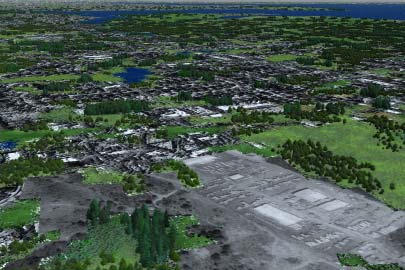
7. Hit F9 or click the Preview Render button ![]() on the toolbar to render the view – you should soon see something like this:
on the toolbar to render the view – you should soon see something like this:
It doesn’t really look like Rhode Island – the Urban textures are simple, tiled, generic urban images that are great for long shots, but don’t hold up to closer inspection. We are going to look at replacing this section of Urban texturing with a more accurate Aerial Photograph of the actual area involved.
8. You can get free orthophotos of Rhode Island at various resolutions from the USGS The National Map site but we have provided one for this tutorial on the CD-ROM. Run a file browsing utility and navigate to your NLCD CD – there you should find a folder called OrthoPhotos. Copy the files named 1240.jpg and 1240.jgw to your WCSProjects:NLCDTutorial2 folder.
9. 1240.jpg is a 1-m orthophoto that focuses on the area we are viewing from NLCDTutorialCamera 2. 1240.jgw is the corresponding World file, containing georeferencing information. The world files located at the aforementioned site are all in Feet, but we needed our world file in meters for VNS to interpret it properly. So the version you have on your CD has already had all values in it multiplied by 0.3048 to convert them from feet to meters.
10. Open the Image Object Library by clicking its button on the toolbar ![]() .
.
11. When the Library interface appears, click the Add Image Object to Library button ![]() to the right of the words Image Object.
to the right of the words Image Object.
12. When the file requester appears, navigate to your NLCDTutorial2 Folder and locate the file 1240.jpg that you copied there in Step 8. When prompted to use the new coordinate system for viewing and rendering, say No.
13. In fact, the coordinate system assigned to the image is completely incorrect! Since the world file contains no specific information about the projection of the image, only its dimensions and location, VNS assumes that the image is UTM – NAD 27. In fact, this image is in State Plane Rhode Island – NAD 83, and we must set that up if we are to have the image correctly align with features on the terrain model, and in the NLCD color map.
14. While the Image Object Library is still open and 1240.jpg is still selected, click on the Georeference tab. You should see the coordinate system defined as UTM – NAD 27, as mentioned before.
15. Click the Edit button ![]() to the right of the Coordinate System dropdown list. The Coordinate System Editor will appear – when it does, click the System tab.
to the right of the Coordinate System dropdown list. The Coordinate System Editor will appear – when it does, click the System tab.
16. Click the System dropdown list and select State Plane – NAD 83, then from the Zone dropdown list that will appear, select Rhode Island. Once you have finished, the interface should look like this:
When you are done editing, close both the coordinate system editor and the Image Object Library.
17. Now we are going to create a new ecosystem that we will use to selectively replace areas of the generic urban imagery. Click the Landcover Task Mode button ![]() and select the Ecosystems category.
and select the Ecosystems category.
18. Click the Add selected item button above the Scene-At-A-Glance ![]() to add a new ecosystem – we are going to configure this ecosystem from scratch, so close the Component Gallery when it opens.
to add a new ecosystem – we are going to configure this ecosystem from scratch, so close the Component Gallery when it opens.
19. You should be left with a new Ecosystem Editor for an ecosystem called Ecosystem. Rename this ecosystem Aerial Photo Ecosystem by typing it into the Name field.
20. Click the Material & Foliage tab.
21. Click the Texture Edit button ![]() to the right of the color well marked Diffuse Color
to the right of the color well marked Diffuse Color
22. Select Create Texture from the menu that appears – it’ll be the only option at this stage. The Texture Editor will open.
23. The texture displayed will be Fractal Noise, since this is the default, but we want our orthophoto, so click the dropdown list below Selected Element and scroll up the list until you find Planar Image.
24. In the section marked Image Object, click the dropdown list and select 1240.jpg
25. The only other thing to do is to click on the checkbox marked Geographic Bounds to select it. This tells our texture to use the georeferencing information in the JPEG world file, rather than arbitrary coordinates defined by VNS. Every other setting can be left at its default. Close the Ecosystem Editor once you are done.
26. We are going to selectively apply this image to areas of our view by bounding the ecosystem with a vector. Since we never closed it or cleared it, you should still have the render that you did in Step 7 available in a view. If not, create another preview render, to use as a guide.
27. Select the Aerial Photo Ecosystem in the Scene-At-A-Glance and click the vector Create button ![]() on the toolbar. Make sure that the digitizing settings are set to Single and click successive points in the rendered preview to digitize a new vector around a foreground urban area. If you feel happier working in a planimetric view, you can zoom to the area in front of the camera, and again, use a preview render to determine where urban areas will appear. Once you have finished digitizing, click the right mouse button and call the vector Foreground Urban 1.
on the toolbar. Make sure that the digitizing settings are set to Single and click successive points in the rendered preview to digitize a new vector around a foreground urban area. If you feel happier working in a planimetric view, you can zoom to the area in front of the camera, and again, use a preview render to determine where urban areas will appear. Once you have finished digitizing, click the right mouse button and call the vector Foreground Urban 1.
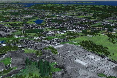
28. Repeat this process for any other urban areas in shot that you wish to show real orthophotos in, instead of the generic texturing. When you are finished, do another preview render. Here’s how mine looked after I had attached the new ecosystem to 1 foreground vector:
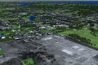
31. Now we shall try and blend the edges of the vector-bounded ecosystem into the surrounding colormapped ecosystems. Click on the Use Profiles checkbox to select it and then click on the Edit Profile button ![]() to open the Profile Editor.
to open the Profile Editor.
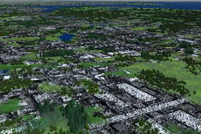
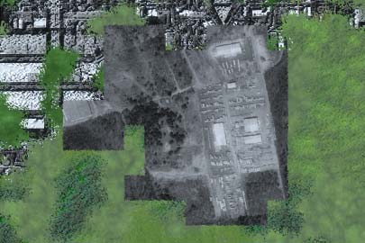
32. The NLCD colormap is 15-m resolution, so I suggest we set our cross section distance to that value – this will merge the vector-bounded ecosystem over the distance of 1 pixel on the colormap. Select the rightmost point on the cross section profile curve and enter 15 m into the Distance box at the top of the interface:
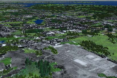
The difference is subtle, but definitely an improvement – compare especially the right hand edge of the industrial area to the bottom right of the frame.
33. Finally, let us add some texturing to the ecosystem, so that it matches more closely the generic texturing. We are going to do this through the use of bump mapping. In the Aerial Photo Ecosystem editor, click on the Material & Foliage tab. Rather than set up a completely new texture for the bump map material attribute, we are going to use the copy and paste functions: click on the Texture Operations button ![]() to the right of the Diffuse Color well. Select Copy Texture from the menu that pops up. Click on the Texture Operations button
to the right of the Diffuse Color well. Select Copy Texture from the menu that pops up. Click on the Texture Operations button![]() to the right of Bump Map Texture, and when the menu pops up, select Paste Texture. In the dialog that follows, you are asked to which material channel you wish to apply the pasted texture – select Bump Map (Root Texture) and click Apply.
to the right of Bump Map Texture, and when the menu pops up, select Paste Texture. In the dialog that follows, you are asked to which material channel you wish to apply the pasted texture – select Bump Map (Root Texture) and click Apply.