3DNature

3D Landscape Design & Visualization Software published and supported by AlphaPixel

Menu

Part 6E. Terraffector Streambed

Getting Started with VNS 3: Lakes & Streams

Part 6E. Terraffector Streambed

1. Open the Plan View Preferences to the Overlay/Gradient page, and select Contours. This will make it easier to trace a drainage.
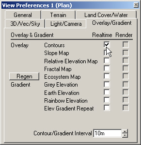
Screenshot of the View Preferences 1 (Plan) window showing settings for Overlay & Gradient, with Contours checked under Overlay. Contour/Gradient Interval is set to 10m.

2.We’ll need room to digitize the stream, so undock the Plan view and drag it out to enlarge it.
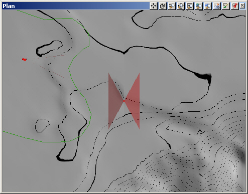
A gray topographic map is displayed on a computer screen with black contour lines, a red triangular overlay at the center, and some green outlines. Toolbar icons are visible at the top.

3. Like Lakes, Streams are a 2-step process. First, we’ll dig a streambed into the terrain with a linear Terraffector. Then we’ll add a Stream.

4. Go to the Terrain Task Mode, select the Terraffectors category, and Create.
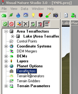
A screenshot of Visual Nature Studio 3.0 interface with a sidebar displaying options such as Area Terraflectors, Control Points, Coordinate Systems, and other terrain-related tools.

5. Turn to the Mouse page and select the Single drawing mode.
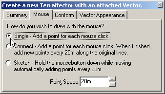
Dialog box titled "Create a new Terrafector with an attached Vector," showing tab options and mouse drawing methods: Single, Connect, and Sketch. The Point Space field is set to 20m.

6. Click on the Plan view titlebar to bring it forward if it’s hidden. Start inside the Lake vector in front of the Lake View Camera and left-click points along low points in the terrain.
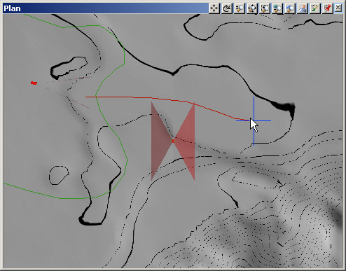
Screenshot of a topographic mapping software displaying contour lines, a red and green line, and a red X mark indicating a selection or point of interest.

7. Right-click to finish and name the vector Stream.
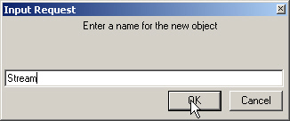
Dialog box prompting to enter a name for a new object, with the name "Stream" typed in the input field and the cursor over the OK button.

8. Add it to the Stream Terraffector.
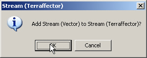
A prompt asks, "Add Stream (Vector) to Stream (Terraffecter)?" with options "OK" and "Cancel." A cursor is pointing at the "OK" button.

9. We could use one of the many provided Components, but we’re going to make our own. Close out the Component Gallery and dock the Plan view.

10. Like an Area Terraffector, a Terraffector uses a profile to control the way the terrain affected. Unlike an Area Terraffector, a Terraffector is a linear feature based on a vector line, not a closed vector shape. Edit Cross-section Profile in the Terraffector Editor.
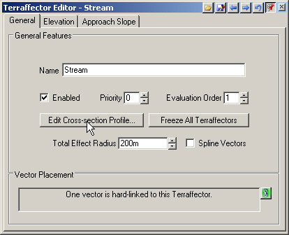
Screenshot of the Terraffector Editor with tabs for General, Elevation, and Approach Slope. Displays settings for enabling, prioritizing, and editing a stream, with a message about vector placement.

11. There is no default profile here; we build it entirely from scratch. The leftmost point is the vector. Terrain will be affected outward on both sides and the ends based on this profile. Change the Value to –3 meters and Tension to 1. This is the centerline of the streambed.
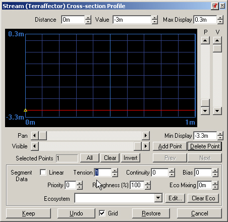
A software interface window titled "Stream (Terraeffector) Cross-section Profile," displaying graph controls, input fields, and adjustment options for modeling a cross-section profile.

12. Add Point and click on the graph, and repeat, to add 2 new points anywhere along the profile. Change the Distance on the rightmost point to 15 meters, make the Value 0, and change the Tension to 1. This is the edge of the streambed. Fifteen meters out from the vector the Terraffector will no longer effect the terrain.
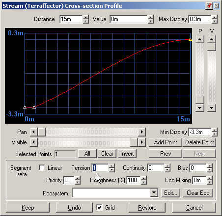
A software interface displays a cross-section profile graph with controls for adjusting various parameters like distance, value, tension, and roughness.

13. Select the second point and change its Distance to 10 meters. Click and drag it up to create a cross-section something like this. If you want to move the point left or right, hold the Ctrl key down while you click and drag.
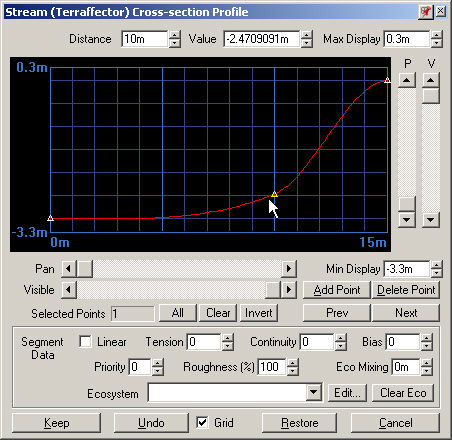
Screenshot of a Stream (Terraffectors) Cross-section Profile interface showing a red curved line graph, various control options, and data manipulation buttons such as "Add Point" and "Delete Point.

14. Keep the profile and go to the Elevation page. Change the Elevation Type to Relative to Vector Elevation and Comparison to Decrease Only.
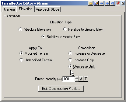
Screenshot of Terraffector Editor - Stream dialog box displaying settings for elevation adjustments, including options for Absolute Elevation, Relative to Ground Elev, and Decrease Only comparison.

15. Save the project and render a preview.
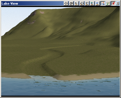
A 3D model of a lakeside landscape with green hills, a winding path leading to the water, and an interface bar on top labeled "Lake View.

16. If your streambed has sharp turns in it, turn to the Terraffector Editor General page and enable Spline Vectors.
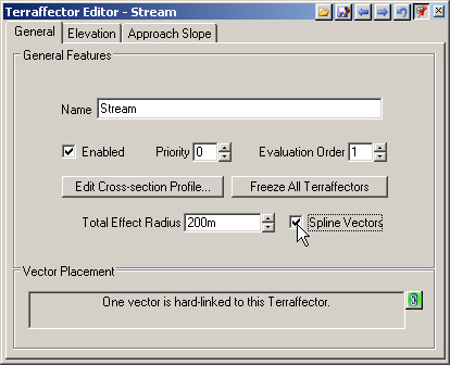
Screenshot of the Terraffector Editor with the stream tab selected. General Features include Name, Enabled checkbox, Priority, Evaluation Order, and other editable fields. Cursor is on "Spline Vectors".

17. Don’t expect your first stream to look as good as your first ocean. Streams are small features that cut into terrain that usually doesn’t have stream-size detail.

18. Alt+click the Stream Vector in the Plan view to activate it.

19. Show Points from the toolbar to make them visible in the realtime Plan view. By default, they’re all selected and show up red.
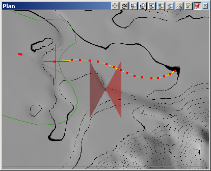
Computer screen displaying a software interface with a topographical map. The map features various contoured lines, a highlighted path, red markers, and several tool icons on the toolbar.

20. To see what the vector profile looks like, bring the Database Editor forward and Edit Vector Profile
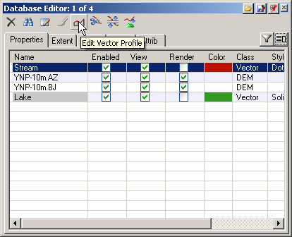
Screenshot of the Database Editor interface showing property details for various vector profiles. The table includes fields such as Name, Enabled, View, Render, Color, Class, and Style with checkmarks.

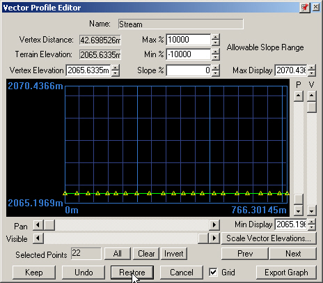
21. The Vector Profile Editor shows elevation on the vertical axis and distance along the vector on the horizontal axis. The vector is represented by the red line and the ground appears in green. In this case, most of the vector is hidden behind the terrain.
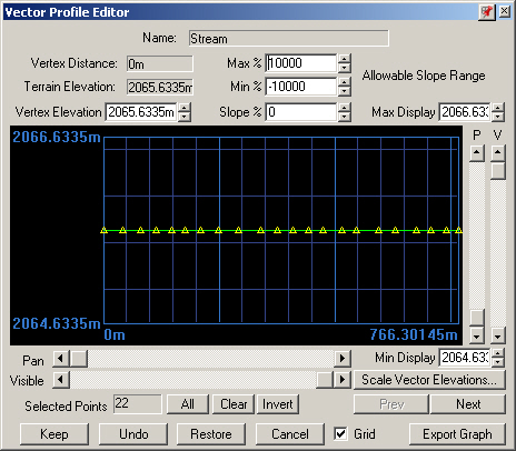
Screenshot of a Vector Profile Editor window showing elevation data. The graph displays a straight line with vertex elevations marked, alongside controls for panning, zooming, and exporting the graph.

22. All the vertices are currently active. Use the Next button to activate just the second vertex, at the lake end of the stream. Increase the Vertex Elevation to 2070 meters.
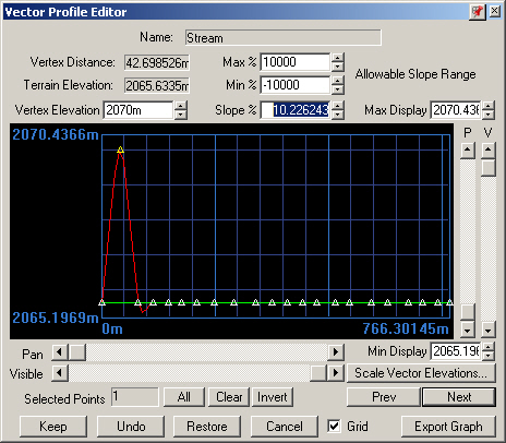
Screenshot of the Vector Profile Editor software window displaying a red elevation graph, numerical data, and various control buttons for editing vector profiles.

23. Render a preview. As expected, the vertex has been raised high enough that the Terraffector no longer has an effect at that point. The Terraffector is set to decrease only so the terrain is not modified above its non-Terraffector elevation.
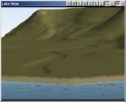
A screenshot showing a computer-generated landscape with a green hillside and a body of water labeled "Lake View" at the top. Various tool icons are visible on a toolbar above the image.

24. Restore the profile to its original state and close the editor.
A screenshot of the Vector Profile Editor software interface showing a graph with vertex elevations and terrain elevation details. Various controls and input fields are visible on the screen.
Scroll to top
Skip to content