3DNature

3D Landscape Design & Visualization Software published and supported by AlphaPixel

Menu

Part 6C. Area Terraffector Lakebed

Getting Started with VNS 3: Lakes & Streams

Part 6C. Area Terraffector Lakebed

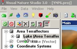
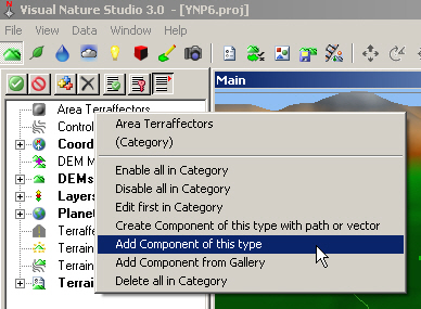
1. Lakes are a 2-step process if you’re not filling an existing depression. You dig out a lake bed with an Area Terraffector and add water with a Lake. Go to the Terrain Task Mode. Like many Components so far, we could use the Create button to make a new vector-Area Terraffector combo. But we already have the Lake vector, so select the Area Terraffectors category in the Scene-at-a-Glance and Add Component of this type.
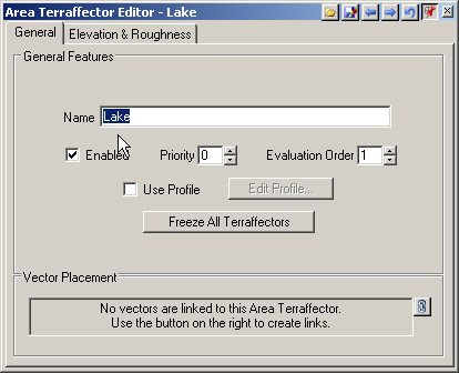
A software window with a dropdown menu opened and the option "Add Component of this type" selected by a cursor in Visual Nature Studio 3.0.

2. Name it Lake.

Screenshot of the Area Terraffector Editor interface for "Lake," with options for general features and vector placement visible. A cursor hovers over the "Enabled" checkbox in the general features section.

3. Expand the Area Terraffectors category.

Screenshot of the Visual Nature Studio 3.0 interface, showing a project file named [YNP6.proj]. The software features various graphical and menu icons, with "Lake (Area Terrafactors)" highlighted.

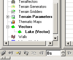
4. Move down to the lower Scene-at-a-Glance list and expand the Vectors category.

Computer screen displaying a software interface with a navigation panel showing options like "Terrain Parameters" and "Lake (Vector)" under the "Vectors" section.

5. Click and drag the Lake Vector up and drop it on the Lake Area Terraffector. Confirm the operation.

A screenshot of Visual Nature Studio 3.0 software interface, showing dropdown menus and resource icons. A selection box is highlighting "Lake (Area Terraflectors)" and "Control Points.

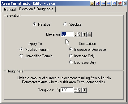
6. Go to the Elevation & Roughness page. An Area Terraffector will raise or lower terrain depending on the Elevation and whether it’s Relative to ground or an Absolute value. Leave the Lake Relative and make the Elevation -50 meters to dig a hole 50 meters below the terrain.

A screenshot of the Area Terraffector Editor interface, showing options for adjusting elevation and roughness settings with various controls and selection options.

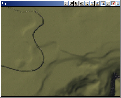
7. Save the project and render a Plan preview.

A computer screen displaying a terrain map with an irregular, winding line, likely indicating a path or boundary, and some toolbar icons at the top.

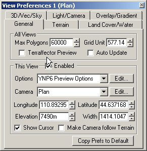
8. Switch back to realtime mode. VNS has Terraffector Preview that you can turn on from View Preferences. This can be useful when working with close views on small sections of high-resolution terrain. For large area effects, memory demands and detail limitations of realtime preview usually make preview renders a better choice.

A dialog box titled "View Preferences 1 (Plan)" with options for adjusting preferences related to polygon limits, grid units, camera settings, elevation, and more.

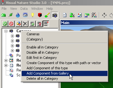
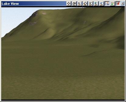
9. Let’s load another camera at the east end of the lake. Go to the Render Task Mode, Cameras category, and Add Component from Gallery.

A software interface with a drop-down menu selected, showing options including "Add Component from Gallery." The cursor is pointing to this option. The application is called Visual Nature Studio 3.0.

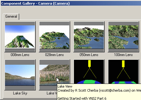
10. Load the Lake View.

A software interface showing a component gallery with lens options and images of landscapes. A tooltip displays "Lake View" and "Created by R Scott Cherba.

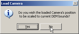
11. Do not scale the Camera’s position to the current DEM bounds.

Popup window with the message: "Do you wish the loaded Camera's position to be scaled to current DEM bounds?" Two buttons below the message say "Yes" and "No," with a cursor pointing at "No.

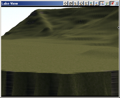
12. Open the Lake View Camera in the upper left view. Save the project and render a preview.

A computer-generated landscape with a hilly terrain viewed in a software interface, labeled "Lake View" at the top.

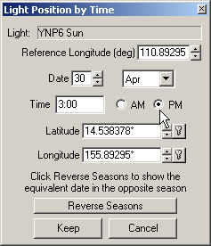
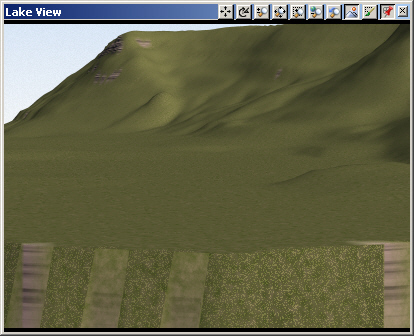
13. We can’t see much with the default morning light. Go to the lower Scene-at-a-Glancepane and open the Light Editor. Turn to the Position & Orientation page and change the time of day to 3:00 pm. Save the project and render a preview.

A dialog box titled "Light Position by Time" showing settings for date, time, latitude, and longitude, with options for AM/PM and buttons for "Reverse Seasons," "Keep," and "Cancel.

14. By default, Area Terraffectors raise or lower terrain with a vertical cliff. To create a gentle slope inward from the vector, we need an Edge Feathering Profile.

A digital rendering of a grassy mountainous landscape, viewed from a low angle. The image is labeled "Lake View," with a toolbar visible at the top edge, suggesting a software interface.

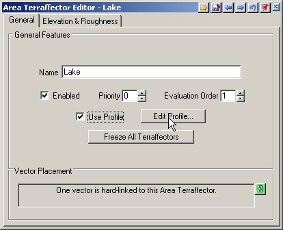
15. Bring Area Terraffector Editor forward. Turn to the General page, select Use Profile, and Edit Profile.

Screenshot of the Area Terraffector Editor for a project named "Lake." Shows settings for priority, evaluation order, and options to use or edit the profile. A note indicates one vector is hard-linked.

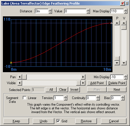
16. For an Area Terraffector, the profile starts at the vector on the left side of the graph. As we move right along the curve, we’re moving inward the vector. Think of the vertical scale Value as a percent of the Elevation we set, in this case -50 meters.

An interface showing the "Lake (Area Terrafector) Edge Feathering Profile" with a graph plotting effect intensity vs. distance. Controls for adjusting the graph and a section for point manipulation are visible.

17. The default profile starts at Distance 0 and Value 0. That means no elevation change at the vector. The profile ends at a Distance of 10 meters and a Value of 100. That’s a full elevation change 10 meters in from the vector. That would be rather steep for our lake.

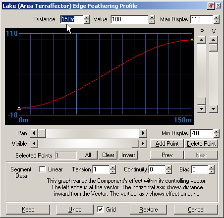
18. Select the right point and change its Distance to 150 meters, which would be more appropriate for a 50-meter-deep lake.

A screenshot of a software interface displaying the Edge Feathering Profile for a lake. The graph shows a curve with distance on the x-axis and the feathering effect on the y-axis.

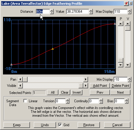
19. Select Add Point and click on the profile. Change the Distance to 60 meters.

A computer interface displaying a graph for "Lake (Area Terraffector) Edge Feathering Profile," featuring adjustable parameters and various control buttons for managing the graph's points and visibility.

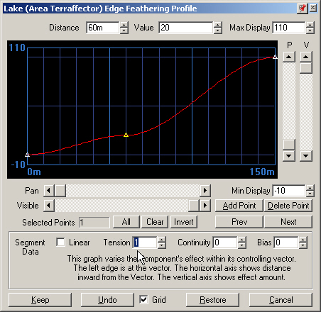
20. Change the Value to 20 and the Tension to 1. The lake bed will slope down to a depth of 20% of 50 meters, or 10 meters, flatten off briefly, then drop to its 50-meter maximum.

A software interface displaying an edge feathering profile graph with controls for segment data, angle, and tension. The graph varies the component's effect within its controlling vector.

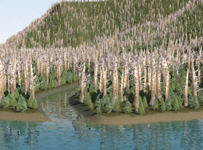
21. Keep the profile, save the project and render a preview. We now have a shallow slope at the edge of our lake bed.

A computer-generated landscape with green hills under a clear sky, displayed within a window labeled "Lake View" in simulation software.
Scroll to top
Skip to content