1. One of the reasons that VNS can render a large terrain in a reasonable amount of time is that it renders the terrain surface differently than traditional 3D programs. To see this, we’ll need to get a closer look at the terrain.
2. Zoom into the TG Camera view with 3 taps of the + key.
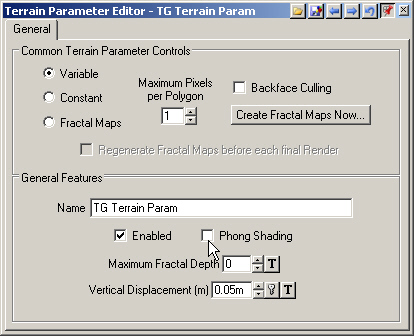
3. Save the project and render a preview. Terrain polygons were rendered at a Maximum Fractal Depth of 0, the default.
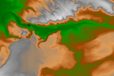
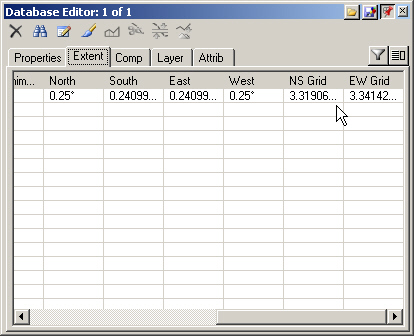
4. Go to the Database Editor and turn to the Extent page. Slide right until you get to the Grid values. Each Grid Cell is about 3.3 meters on a side.
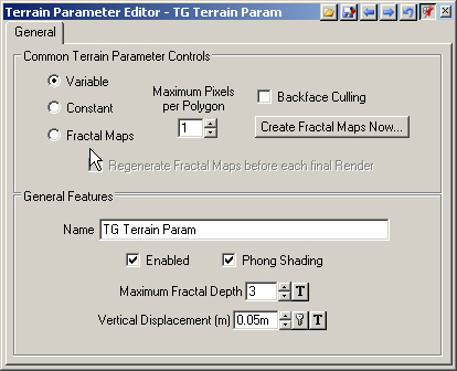
5. At a Fractal Depth of 0, each grid cell is rendered as 2 polygons. We can’t really see the polygons because VNS 3 has an amazing new phong shader for terrain. Go to the lower S@Gpane and open the Terrain Parameter Editor. Deselect Phong Shading.
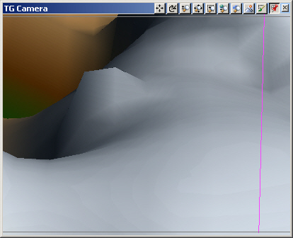
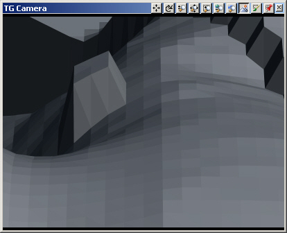
6. Open another TG Camera view in the upper right quad and render a preview. Now we can see the polygons.
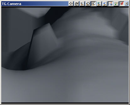
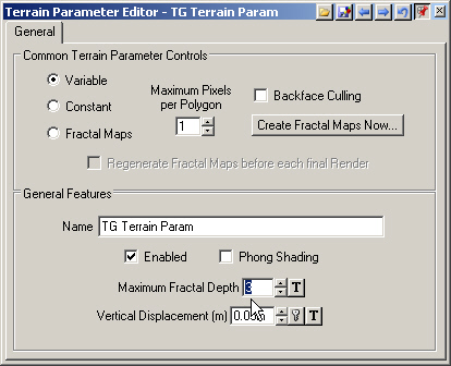
7. With each increase in Maximum Fractal Depth value, each rendered polygon is further divided into 4 polygons. At a Fractal Depth of 0, each grid cell is divided into 2 polygons. Increase the Maximum Fractal Depth to 3.
8. Save the project and render another preview in the upper right view. We’ve gone from 2 polygons per grid cell at Fractal Depth 0 to 128 polygons per grid cell at Fractal Depth 3.
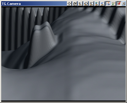
9. Enable Phong Shading and render the same preview again.
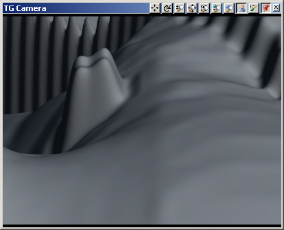
10. Increase the Maximum Fractal Depth to 7. Activate the left view and render a preview.
11. Each original polygon in the left Fractal Depth 7 view has been rendered as more than 16,000 polygons, each only a few centimeters on a side. But we’ve gained almost no apparent detail at the cost of an increase in render time. The new phong shaded terrain means you’ll be able to use a much lower Fractal Depth than VNS 2 and have better looking terrain and shorter render times. Reduce the Maximum Fractal Depth to 3.
12. Now that we know what Fractal Depth is, let’s talk about the 3 ways of rendering it. In the Terrain Parameter Editor, the default Fractal Depth method is Variable. This renders near polygons at a higher Fractal Depth, where we can see them, and decreases Fractal Depth with distance. Variable Fractal Depth is a good choice for still images where accurate foliage shadows aren’t needed. Constant Fractal Depth renders the same Fractal Depth everywhere, which will significantly increase render time. Fractal Maps are Variable Fractal Depth for animations. Fractal Maps are also the best choice when accurate foliage shadows are needed in still images. When Fractal Depth Maps are created, VNS maps near and far polygons along camera paths in Render Jobs.
13. While we’re talking about terrain detail, let’s look at bump mapping. Bump mapping can be applied to the terrain via a Ground Effect. It can increase the realism of the terrain surface.
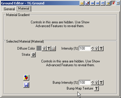
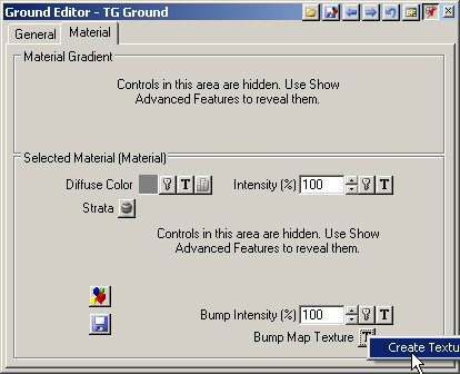
14. Go to the Land Cover Task Mode. Open the Ground Editor to the Material page. At the bottom of the Selected Material section are two bump map parameters, Bump Intensity and Bump Map Texture.
15. Select Bump Map Texture Texture Operations and Create Texture.
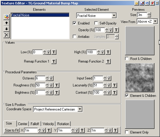
16. The default texture is Fractal Noise with a Size of 1 meter along the X, Y, and Z axes. Close the editor.
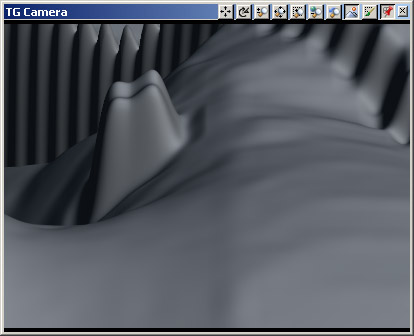
17. Save the project and render a left view preview. Even with a simple default texture, the terrain looks more convincing.
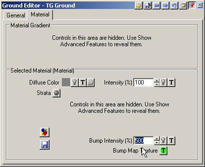
18. Increase the Bump Intensity to 500%.
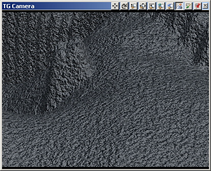
19. Activate the right view and render a preview. This is much more Bump Intensity than you’ll normally use, but you don’t know how much is too much until you try it.