
3D Nature Frequently Asked Questions
Add-on Tools
Explore Scene Express projects with NatureView Express, the free realtime viewer created by 3D Nature. NatureView Express is included with Scene Express and may be redistributed with no additional licensing costs. This allows Scene Express users to publish projects and send them to clients and other interested parties with NatureView Express included to explore the scene. NatureView Express can also view projects on the Internet in a web browser.
More info about NatureView is available.
Scene Express is 3D Nature’s tool that allows the export of terrain and landscape elements for use in realtime engines or for final rendering in other 3D packages.
Learn more or see a wide variety of images here.
The Forestry Edition for VNS was created at the request of our many Forestry Customers. They wanted a tool that would directly connect their forest stand and polygon attributes to their visualization with a few easy clicks of the mouse.
You can learn more about this tool and see some images created with it here.
The NLCD Content CD is actually a 2-CD set with one VNS Template project, supporting texture image files, and compressed GeoTIFF raster images for the lower 48 US states. This product relies on the Templates feature and is only compatible with VNS.
For more information or to view images created using this data click here.
This DVD-ROM contains the best quality, highest resolution collection of terrain, bathymetry, color imagery and cloud maps that we could assemble that covers the entire planet.
Ultimate Earth contains 1-kilometer land mass terrain data, 10-kilometer bathymetry, 1-kilometer color imagery and 5-kilometer cloudmap data for the entire globe. The DEM data alone contains well over 939 million data points. The imagery contains over one billion pixels.
This DVD-ROM also contains over a dozen projects that allow you to work with a smaller area of the earth (saves memory and hard drive space) and Components that allow you to apply this image data to your current projects.
Click here to see sample imagery or learn more.
Buying WCS or VNS
All of the parts that are included in our products have been verified to be compliant.
Yes you can! Contact us at 303-659-4028. We will review your information to see if our companies are a good match. We can also add you (and your Web Page) to our Online Dealer Network so customers can find you quickly!
Visual Nature Studio can also be conveniently be purchased from your favorite software distribution sources. If they do not carry VNS, ask them to contact us!
Yes you can! 3D Nature sells Visual Nature Studio to users worldwide. You can order from the Store or call the Sales Office at (303) 659-4028. We can also direct you to a dealer in your area. Visit our Online Dealer List.
3D Nature does not generally accept returns on software. Please make sure you really want our product before ordering it.
If, under extenuating circumstances a return is authorized by one of our Managers, that product must be in the original unopened packaging, including all parts, undamaged in any way.
If a return is accepted a 15% restocking fee will be charged. Additionally, you will not be refunded for the original shipping charges and you will be responsible for shipping the product back to 3D Nature at your expense.
See our Availability, Pricing and Upgrades page for pricing and availability for announced versions. If it is not on the list, then we’re not talking about it yet! Stay tuned to our web site for more details.
Right here! Registered users can obtain program updates online via our Internet Update System after Registering their copy of VNS.
Delivery and Shipping
3D Nature is proud to have a world-wide user base.
When a product is shipped outside of the Untied States we will ship it via whatever service method the recipient prefers. Due to reliability and billing issues, we currently only offer services through FedEx. Although we can offer average delivery time for each service we are not able to guarantee these times due to occasional international shipment delays that are beyond our control.
All international duties and taxes are the sole responsibility of the recipient.
Features and Capabilities
Yes! Visual Nature Studio includes powerful tools for drawing or importing control points and using them to grid new terrain shapes. The points can define contours, ridgelines, peaks, dips, valleys, watershed/drainage basins or any other topographic features.
The new Terrain Generator allows users to create their own terrains. Use the power of the texture editor to design a heightfield, and have VNS turn it into a DEM of whatever resolution you require.
Yes. For Image Object trees you can modify any picture to add your favorite local species of foliage! Tips for creating foliage objects can be found here.
Definitely! VNS can animate hundreds of different terrain, foliage, texture, water, cloud, atmosphere, sky, celestial object, light, shadow, 3D object and camera attributes. Our keyframe animation system is spline-based with precise control of key frames, tension, continuity and bias on every motion channel individually. For your convenience, you can also simultaneously create key frames for related groups of parameters together, such as all three camera position parameters.
You can create roads of all types, from simple paths to multi-lane super-highways, with our exclusive Terraffector™ technology. VNS will even manage the terrain modification (cuts or fills) to maintain the road centerline elevations you specify.
Terraffectors are useful for more than roads. They can make dams, runways, golf course features, baseball diamonds, and much, much more.
Perhaps the best thing about Terraffectors is that the changes don’t really alter the terrain model. They only alter its rendered appearance. So any changes are instantly reversible. You can tweak the effect until you get just what you want without worrying about wasting disk space with multiple copies of the DEM.
Another important advantage is that they work on fractally-subdivided terrain. You don’t need highly detailed terrain models to get detailed topographic effects. The detail is added at rendering time only in the areas where it is needed. This is a big benefit when most of the scene doesn’t need extreme detail.
Yes. VNS lets you import 3D Objects created in LightWave, MAX, Onyx Tree Professional, Tree Druid, LSYSTEMS or any other program that can create objects in LightWave, 3D Studio, Wavefront OBJ or DXF format.
3D Objects can receive shadows, be self shadowed and cast shadows on other 3D Objects and the terrain. They reflect in water. You can animate size, position and rotation on any axis. You can place 3D Objects at specific places on the terrain with georeferenced host vectors using the 3D Object Effect.
For surfaces, VNS recognizes object color, luminosity, transparency, specularity, single- or double-sided rendering and shading. You can choose from flat or phong shading. VNS supports Bump Mapping and UV mapped bitmap image textures to make your 3D Objects more realistic!
You can animate and texture color, luminosity, specularity, transparency and translucency with the powerful VNS Texture Engine. The Texture Engine lets you combine a variety of procedural textures to create looks like brick, rock, dirt, metal, plastic and water, along with image-based texturing. Translucency controls let you simulate light transmission, which is great for realistic sunlit leaves.
You can also add non-landscape objects to your animation by modeling and rendering them in a general-purpose 3D package and using our Z-Buffer Compositing to merge them together seamlessly. This is particularly useful for character animation, aircraft or objects that you need to render using specific features of another package.
At this time, VNS does not do volumetric analysis. A number of the natural-variety adding features of VNS would actually degrade the precision of any analysis calculations of this sort, so we do not currently attempt to address these capabilities.
Yes! Visual Nature Studio has advanced antialiasing built right into the renderer. In addition we offer Box Filtering, Z-Buffered Edge Softening, and Multi-Pass antialiasing with sub-pixel offsets. Plus, we have Field-Rendering for smooth 60fps video, and built in user-controlled Motion Blur.
At this time, VNS does not perform Viewshed Analysis calculations. While calculating Viewsheds for simple surfaces is a well-known art, Viewsheds incorporating more advanced capabilities such as foliage occlusion, lighting and contrast consideration, distance weighting and other perceptual factors are considerably more difficult. 3D Nature does not feel that a simple bare-surface Viewshed analysis adds any value for our users, but we may in the future implement visibility analysis if we can create a method that incorporates vegetation and other factors we feel are critical.
Import and Export
Yes! If you have contour data available in a compatible vector format you can import the data, assign elevations to the contours and use them to grid a DEM in VNS. For files with over 6,000 points, VNS is much faster at the gridding process.
Yes. You can drape satellite or other remote-sensed imagery over the terrain. You can directly project a picture onto the terrain, or even use the colors in an image to control where different ecosystems appear. Ecosystems include overstory foliage, understory foliage and ground texturing.
VNS can use trees of several types. The efficient and realistic Image Object trees are essentially 2.5D objects composed of textures shaded onto generic 3D forms. 3D shading gives them their realistic volumetric look. These trees cannot directly be used by other 3D packages in the same manner since other software lacks the ability to render them this way.
VNS can also import and render true 3D trees in LightWave, MAX, DXF and OBJ formats. If you have trees in these formats, other packages might also be able to use them. However, only VNS gives you the ability to render luminosity for realistic light transmission by leaves. VNS also gives you the ability to plant many trees automatically based on Rules-of-Nature™ for fast and realistic Ecosystem distributions.
Update: The new Scene Express add-on for VNS allows for more full-featured export to a variety of formats, including pre-shaded tree images!
VNS can import the following 3D Object types: LightWave 3D, 3D Studio, DXF, Wavefront OBJ, and VNS 3D Object geometry files (extension “.w3o” or “.w3d”).
DEMs, which stands for Digital Elevation Models, define the shape of the terrain. VNS lets you visualize real places and can import DEM data in a wide variety of standard DEM formats.
The amazing new Import Wizard makes this much easier. It will identify your data and walk you through the simple steps needed to load it.
Currently VNS can read: Arc ASCII DEM, Arc USGS ASCII DEM, ASCII Array, Bryce v2, v3, v4, Binary Array, DTED, DXF, GTOPO30, Images (BMP, IFF, PICT, Targa, JPEG, PNG and TIFF), NED BIL (National Elevation Dataset), NED Grid-Float, SDTS DEM, STM (Simple Terrain Model), Terragen, USGS ASCII DEMs, VistaPro DEMs and WCS or VNS DEM. Additionally VNS can use ECW, UK NTF and Arc ADF and E00 raster data.
The Import Wizard can also read almost any form of regular-interval data (spreadsheets, raw data files, images, etc.) and create new DEMs under your control. You can even use the Import Wizard to interpolate and tile your data.
Scene Express for VNS outputs NatureView, VRML, VTP, Google Earth KML, 3D Studio (PRJ), Lightwave LWO and Alias FBX. Additionally, Scene Express for VNS offers export to GIS (ESRI DEM + GeoTIFF) and VNS.proj. Some optional add-on formats can be purchased for VNS, including STL (Stereolithography)/VRML-for-STL and OpenFlight (FLT). Sample output for some of these formats is available here.
Currently VNS read and write Targa (TGA), Windows BMP, IFF, PICT, JPEG, PNG, Radiance RGBA/HDR, AVI, Quicktime, and TIFF. It also generates RLA and Sculpt/RAW/RGB files. VNS can also write a variety of rendered data to ECW, Arc Grid BIL and Arc GRIDFLOAT. Support for other formats is planned in the future.
Vectors let you position VNS components onto the terrain. For example, you can use vectors to place roads, lakes, trees, entire forests, clearings, flat building sites, mountains and much more.
VNS can import ESRI 2D & 3D Shapefiles; AutoCAD DXF or XYZ files in Lat/Lon, UTM or arbitrary coordinates (VNS supports over 30 different projections as well) and USGS ASCII DLG files. The new Import Wizard will detect the data type automatically!
VNS can automatically group your shapefiles into layers, for easy, automatic assignment of Ecosystems.
You can create control points interactively with your mouse or import existing data from a file. VNS supports AutoCAD DXF files, ArcView Shape files and DLG files.
The gridding process is much like ‘draping’ a sheet across points in 3D space to create the terrain surface.
VNS also includes an easy-to-use fractal landscape generator that lets you create terrain with a single click. You can control various attributes to generate different types of terrains.
The new Scene Express add-on for VNS allows for more full-featured export to a variety of formats.
Visual Nature Studio is capable of writing a landscape out to LightWave 3D and 3DStudio/Max formats. Other packages are under consideration. The landscape objects are meant for reference use. They make it easier to see where your 3D objects will appear in relation to the terrain as you place the 3D objects (buildings, vehicles, characters etc.) using the external 3D program.
The actual landscape rendering is done in VNS where millions of polygons and thousands of trees are no problem. The fully rendered VNS landscapes are then composited in 3D using the Z-Buffer plugin in the external 3D program, allowing the 3D objects to go in front of or behind the already photorealistically rendered terrain.
The exported landscape objects are necessarily limited in detail due to polygon limitations in most 3D programs. You can also further downsample the objects on export to increase the display speed in external 3D program.
The landscapes are exported as objects built of 3-point polygons.
The landscape file does not contain any trees or other foliage (see “Can I export trees?” above). The file does contain reference NULL/dummy objects that stand in for any vector objects you might have created in VNS. This allows you to precisely mark a point (or path) in VNS, and then have that exact position translated along with the landscape, into other 3D formats. Placing objects relative to these reference points is as simple as parenting 3d objects to the NULL/dummy object.
Update: The new Scene Express add-on for VNS allows for more full-featured export to a variety of formats.
VNS can import scenes, including camera motion, from LightWave and MAX. VNS can also export scene files in LightWave and 3D Studio formats. Other programs may be supported in the future.
Update: The new Scene Express add-on for VNS allows for more full-featured export to a variety of formats.
VNS currently exports scenes in LightWave and 3DS/Max format. Other packages are under consideration. The Scene file contains camera and (optionally) target motions, light positions, haze distances and other animation information. The combination of scene export and Z-Buffer plug-in support makes it possible to smoothly integrate VNS with external 3D programs.
Update: The new Scene Express add-on for VNS allows for more full-featured export to a variety of formats.
Support and Training
Yes! Check out our Resources section and Scott Cherba’s Landscapes Illustrated for lots of tutorials, hints and tips, DEM sources, and links.
You may also join the International WCS/VNS Mailing List, currently hosted on YahooGroups. This is a great place to ask questions and share VNS tips with members of the development team and VNS artists and scientists from around the world.
Yes! See our Training page for details.
We continue supporting all of our products for a long time after a newer version become available. You can count on having support available on some level for your product for a minimum of two years after the next version is released.
As of August 1, 2003, 3D Nature suspended support for WCS 4. At that time WCS 4 was 2 versions behind the current release and had been out of production (no longer available for purchase) for well over 2 years.
The hardware key is the only way 3D Nature has to make sure that our products are only being used by authorized customers. They are also the only way we have of controlling the number of copies that people are using of our software.
If your hardware key had been lost or stolen, 3D Nature is able to sell you a discounted additional seat of the version of our product that you have that will include a new dongle.
If in the future your original dongle is found or returned you will be able to run two copies of the software legally.
Please note that if your dongle was destroyed or stolen the cost of the replacement seat is often covered under your business or home insurance. See “My hardware key is not working. How do I repair it or get a replacement?” below.
The first thing to do is to make sure you have installed the proper drivers for your hardware key. You can download these from SafeNet.
If you have done that and the key is still not working, download the Sentinel Advanced Medic tool from the same page. When you run this it will tell you if the hardware key has been detected. If it has, try rebooting your system and that may solve the problem. If not please contact our office and we will arrange to have a new key sent out to you.
We will provide free hardware key exchanges (for defective keys) for the current version of any product. If you are running an older version of the software there will be a $50 fee for the dongle replacement. However, if you decide to upgrade to the current version, the fee will be waived.
Yes! 3D Nature periodically offers a 5-day training course. Check out our Training page for information about the upcoming sessions.
Certified Trainers also hold classes at various locations on occasion. Contact 3D Nature for more information or with questions.
Technical Issues
Your Windows OS system should have 2GHz processor speed (Pentium 4 or later, SSE2 required for VNS 3) and at least 1Gb of memory. The full program install of VNS 3 requires 4.4 Gb of hard drive space.
You will also need a True-color (16, 24 or 32-bit) OpenGL capable display running at a resolution of at least 1024×768. Make sure you have the latest display drivers and OpenGL support for your display card. VNS use advanced OpenGL capabilities extensively and will have trouble with outdated or buggy OpenGL support from your display card.
Currently VNS is not multithreaded. However you can use multiple processors to render by running several instances of VNS and adjusting the frame range or step on each to divide the rendering among your processors. This actually works more efficiently than typical multithreaded rendering implementations.
Both programs now include our free Network Render Controller, SuperConductor. For more information about this product please visit http://superconductor.sourceforge.net/. For the most recent SuperConductor tutorial in the VNS HTML format, download the zipfile.
No. Direct3D does not support the high-precision graphics operations that Visual Nature Studio requires. If you are buying a 3D card for graphics work, and you want graphics acceleration, make sure the card you choose supports OpenGL hardware acceleration.
No. Hardware 3D accelerators typically only improve the speed of real-time interaction with 3D objects and terrain in VNS (and other programs). 3D accelerated graphics cards make a VERY significant difference in the performance of realtime landscape viewing tools like NatureView.
VNS requires OpenGL. You don’t necessarily have to have a graphics card with OpenGL hardware acceleration, though one is strongly recommended. If your display card implements OpenGL, VNS requires a good reliable OpenGL driver. Make sure you have updated your video card display driver to the latest available for best performance. VNS supports OpenGL under all versions of Windows.
Not directly, since VNS is not multithreaded (see above). However, one can launch several instances of the program during large render jobs. OS task scheduling on multi-processor systems will assign CPU resources equally between each instance, and will therefore use all of your CPUs effectively.
Both programs now include our free Network Render Controller, SuperConductor. For more information about this product please visit http://superconductor.sourceforge.net/. For the most recent SuperConductor tutorial in the VNS HTML format, download the zipfile.
VNS is a 32-bit application. It will run fine on 64-bit CPUs using the X86-64 instruction set (The AMD64 CPUs or the EMT64 series from Intel). VNS will not run on the Intel Itanium architecture. The hardware key used by VNS is available in parallel port or USB port variants. Only the USB port variant is currently supported on 64-bit Windows at this time. Additionally, due to the newness of 64-bit Windows, not all systems work perfectly even with the USB hardware driver. Contact 3D Nature if you need to exchange a parallel key for a USB key, or if you need the 64-bit drivers.
VNS performs identically on a 64-bit OS as it does on a 32-bit OS. Other than access to greater amount of memory (64-bit OSes can offer a 32-bit application up to 3Gb of address space), there is currently no advantage to running 64-bit Windows. There are numerous disadvantages due to many companies not having drivers up-to-date for 64-bit Windows.
While 3D Nature has tested VNS on 64-bit Windows, we currently have no compelling reason to recommend it for most users. We do recommend that new hardware purchases specify 64-bit capable CPUs, as in the future (within the lifespan of today’s workstation computers) more and more programs will support and take advantage of these capabilities. (Information current as of May, 2006.)
VNS includes a very specialized and efficient terrain renderer that can handle millions of polygons and vast amounts of foliage very quickly. The speedy renderer is designed for production animation.
Current Intel and AMD processors are all very fast, and faster versions constantly become available. In any given month a different system may be fastest.
When you are ready to buy a computer for VNS, get the fastest system you can afford. Compare the floating point performance of the processors you consider. Make sure you have plenty of RAM, with at least 1GB of RAM per core — even more is better. Ask for up-to-date hardware advice on the international VNS mailing list.
When you run VNS without its hardware key, it loads as a Render Engine. By running VNS as a render engine you can use multiple computers to render final animations, saving valuable production time!
Both programs now include our free Network Render Controller, SuperConductor. For more information about this product please visit http://superconductor.sourceforge.net/. For the most recent SuperConductor tutorial in the VNS/WCS HTML format, download the zipfile.
Visual Nature Studio is professional software. If you are really into terrain animation you may have more than one terrain program. VNS will happily work with data from other programs. But if you can have only one terrain program, VNS offers the best combination of advanced features and photorealistic rendering quality, all at price so affordable it can pay for itself with a single job.
VNS is the Leader
Visual Nature Studio is the leading GIS-based terrain visualization and animation package. VNS offers a serious set of advanced photorealistic terrain tools for professional use. VNS is the choice of artists and scientists for critical tasks where high quality is important.
Visual Nature Studio is everywhere. You have probably seen see VNS in feature films (such as the Academy Award(R) winning film The Cider House Rules from Miramax); high profile architectural and engineering visualizations (golf courses, shopping centers, mines, dams, etc.); network television animations (CBS, PBS, BBC, HBO, TLC and others); land use planning visualizations (BLM, USDA Forest Service, Ontario Ministry of Natural Resources, California Department of Forestry, and Ministry of Forestry, British Columbia, etc.); mapping and cartography (USGS, National Geographic Magazine, the Washington Post, Hawaiian Airlines, etc.); aeronautics and space exploration visualizations (NASA, JPL, German Aerospace Center, Boeing, Lockheed Martin, Aerospatiale, United Airlines, etc.); and animations and backgrounds for a long list of popular video games.
VNS is also popular on university campuses for architectural and engineering visualization, cartography, natural resource management and scientific simulations. You’ll find VNS at Harvard, Oregon Graduate Institute of Technology, Johns Hopkins, Penn State, and many others.
Other Terrain Software
Many people have moved up to Visual Nature Studio after starting with consumer-level terrain software. Although they may have liked some things about the consumer-level software, they’ve reported finding many limitations, being unsatisfied with the rendering quality and user interaction, and being frustrated with slow rendering times. Some of these programs can only render a limited amount or resolution of terrain. None of them have any concept of location on the actual planet. All of them render terrain as a giant flat table top instead of an actual spherical earth, which means positions, lighting, skies, viewsheds (what you see from any given point), and fly-through animations cannot be accurate.
These various low-end “flat earth” terrain programs are suitable for artistic impressions of landscapes or creating surrealistic scenes. Some render a few things well but you may soon find limitations. A few have useful terrain editing tools. On the plus side, people can gain experience using these tools, and VNS supports many data formats so artists can move up to VNS, bring their terrain data along, and continue to use the other software along with VNS if it makes sense to do so.
If you’re serious about terrain, eventually there will come a time when you will want to move beyond the typically limited feature sets and computer-generated, even flickery feel of low-end software.
VNS let you upgrade your work to a higher sense of realism, a more accurate simulation of the real world, unlimited terrain on an actual spherical planet, smoothly antialiased rendering, and reasonable rendering times for production animation and high resolution print output.
Other 3D Software
Many people have come to VNS after attempting to create realistic landscapes in general 3D programs. But having great tools for making and animating things like cars, dinosaurs and characters won’t really cut it when the time comes to face the very different demands of creating vast areas of believable terrain with realistic foliage distributions, skies, water and clouds.
It is possible to simulate limited terrain in general 3D programs, but it’s not easy. Larger terrains may be entirely impractical due to the sheer amount of polygons and high numbers of pieces of foliage necessary to create a believable scene. This amount of data may overwhelm a typical general 3D program.
VNS offers dedicated and unique tools specifically designed to make creating vast terrains and huge foliage distributions easy. VNS’s powerful terrain renderer is specially designed to handle millions of polygons and huge numbers of trees and other foliage in ways not possible in a general 3D program. VNS can render any amount of terrain, up to and including an entire planet.
Using VNS doesn’t mean you have to give up your general 3D program. VNS includes integration features that let you combine the great VNS terrain rendering with your 3D program’s characters and objects. See also “What is this ZBUF compositing about?”
VNS has proven itself in high profile feature film, network television and game development applications. The output can look so real you may have seen VNS renderings and just assumed you were looking at actual film or video of real places!
VNS is the Complete Choice
For professionals in the GIS, natural resource planning, forestry, engineering, cartography and architectural fields, VNS is the complete choice. For artists, the scientific foundation of VNS offers higher realism and accuracy and opens new markets. Other terrain programs simply lack the advanced features and real-world foundation of VNS.
Currently VNS reads and writes Targa (TGA), Windows BMP, IFF, PICT, JPEG, PNG, Radiance RGBA/HDR, AVI, Quicktime, and TIFF. It also generates RLA and Sculpt/RAW/RGB files. VNS can also write a variety of rendered data to ECW, Arc Grid BIL and Arc GRIDFLOAT. Support for other formats is planned in the future.
DEMs, which stands for Digital Elevation Models, define the shape of the terrain. VNS lets you visualize real places and can import DEM data in a wide variety of standard DEM formats.
The amazing Import Wizard makes this much easier. It will identify your data and walk you through the simple steps needed to load it.
Currently VNS can read: Arc ASCII DEM, Arc USGS ASCII DEM, ASCII Array, Bryce v2, v3, v4, Binary Array, DTED, DXF, GTOPO30, Images (BMP, IFF, PICT, Targa, JPEG, PNG and TIFF), NED BIL (National Elevation Dataset), NED Grid-Float, SDTS DEM, SRTM .hgt, STM (Simple Terrain Model), Terragen, USGS ASCII DEMs, VistaPro DEMs and WCS or VNS DEM. Additionally VNS can use ECW, UK NTF and Arc ADF and E00 raster data.
The Import Wizard can also read almost any form of regular-interval data (spreadsheets, raw data files, images, etc.) and create new DEMs under your control. You can even use the Import Wizard to interpolate and tile your data.
Vectors let you position VNS components onto the terrain. For example, you can use vectors to place roads, lakes, trees, entire forests, clearings, flat building sites, mountains and much more.
VNS can import ESRI 2D & 3D Shapefiles; AutoCAD DXF or XYZ files in Lat/Lon, UTM or arbitrary coordinates (VNS supports over 30 different projections as well) and USGS ASCII DLG files. VNS adds a variety of ASCII text GPS files and .GPX format. The new Import Wizard will detect the data type automatically!
VNS can automatically group your shapefiles into layers, for easy, automatic assignment of Ecosystems.
You can create control points interactively with your mouse or import existing data from a file. VNS supports AutoCAD DXF files, ArcView Shape files and DLG files.
The gridding process is much like ‘draping’ a sheet across points in 3D space to create the terrain surface.
VNS also includes an easy-to-use fractal landscape generator that lets you create terrain with a single click. You can control various attributes to generate different types of terrains.
Yes! If you have contour data available in a compatible vector format you can import the data, assign elevations to the contours and use them to grid a DEM in VNS.
Scene Express for VNS outputs NatureView, VRML, VTP, Google Earth KML, 3D Studio (PRJ), LightWave LWO and Alias FBX. Additionally, Scene Express for VNS offers export to GIS (ESRI DEM + GeoTIFF) and VNS (PROJ). Some optional add-on formats can be purchased for VNS, including STL(Stereolithography)/VRML-for-STL and OpenFlight (FLT). Sample output for some of these formats is available here.
Yes. You can drape satellite or other remote-sensed imagery over the terrain. You can directly project a picture onto the terrain, or even use the colors in an image to control where different ecosystems appear. Ecosystems include overstory foliage, understory foliage and ground texturing. VNS can drape images in many projections (UTM, State Plane, etc.) as well!
VNS can use trees of several types. The efficient and realistic Image Object trees are essentially 2.5D objects composed of textures shaded onto generic 3D forms. 3D shading gives them their realistic volumetric look. These trees cannot directly be used by other 3D packages in the same manner since other software lacks the ability to render them this way.
VNS can also import and render true 3D trees in LightWave, MAX, DXF and OBJ formats. If you have trees in these formats, other packages might also be able to use them. However, only VNS gives you the ability to render luminosity for realistic light transmission by leaves. VNS also gives you the ability to plant many trees automatically based on Rules-of-Nature™ for fast and realistic Ecosystem distributions.
Update: The new Scene Express add-on for VNS allows for more full-featured export to a variety of formats, including pre-shaded tree images!
Version and Pricing
Occasionally we do offer competitive upgrades. Watch our web site for announcements and information about these offers.
We have a Demo Version for Visual Nature Studio 3. You can download it for free and it even includes tutorials!
The Demo Version will not allow you to save your work, preview renderings will have a “rainbow bar” across them, and certain other features are intentionally disabled. A window may appear periodically to remind you that you are using the Demo Version. The Demo version is intended only for you to try the program in order to decide if you wish to buy it. You may not use the preview version to create any finished work.
Qualified educators and students may purchase Visual Nature Studio and Scene Express at a discount. Contact 3D Nature at 303-659-4028 for pricing and qualifications.
VNS includes a USB hardware key. If you require a legacy parallel key, you can arrange this at purchase time by contacting us prior to ordering. If needed at a later date, you can exchange key types for $50. You must return your original hardware key before a replacement can be shipped out to you. Please contact a 3D Nature sales representative if you need to exchange your hardware key.
Extra seats are available for registered users of the current version of VNS. It is another full copy of the same version of VNS with the same Serial Number as your first copy. These are available at a very reduced rate from 3D Nature or a Preferred Dealer. Please contact us for pricing.
Registered users can upgrade to a newer version at significant discounts. We also offer cross-platform upgrades. For more information, contact the 3D Nature Sales office at 303-659-4028. Interim updates are free of charge to registered users. They can be downloaded via the Updates page.
VNS and Other Programs
VNS is a stand-alone terrain rendering and animation programs. VNS is not itself a plugin for any other program.
We do provide several compositing plug-ins for popular 3D packages to facilitate integrating VNS imagery with theirs.
There are a number of reasons. From an economic standpoint, we can offer greater flexibility to our users by not locking them into a particular package or platform. Visual Nature Studio’s powers are available to you without forcing you to buy a particular ‘host’ program to run a plug-in. You can use a variety of general-purpose 3D packages together with VNS, or use VNS by itself to produce the most stunning 3D landscapes you’ve ever seen!
From a technical standpoint, Visual Nature Studio utilizes many innovative rendering techniques. We have developed a number of proprietary algorithms for rendering our landscapes at optimal levels of detail, and have pushed the envelope in the field of antialiasing. Many of these methods would not marry well to the traditional scanline/raytrace 3D packages.
VNS can import scenes, including camera motion, from LightWave and MAX. VNS can also export scene files in LightWave and 3D Studio formats. Other programs may be supported in the future.
Update! The Scene Express add-on for VNS allows for more full-featured export to a variety of formats. The following description applies to without the Scene Express add-on.
Visual Nature Studio are capable of writing a landscape out to LightWave 3D and 3DStudio/Max formats. Other packages are under consideration. The landscape objects are meant for reference use. They make it easier to see where your 3D objects will appear in relation to the terrain as you place the 3D objects (buildings, vehicles, characters etc.) using the external 3D program.
The actual landscape rendering is done in VNS where millions of polygons and thousands of trees are no problem. The fully rendered VNS landscapes are then composited in 3D using the Z-Buffer plugin in the external 3D program, allowing the 3D objects to go in front of or behind the already photorealistically rendered terrain.
The exported landscape objects are necessarily limited in detail due to polygon limitations in most 3D programs. You can also further downsample the objects on export to increase the display speed in external 3D program.
The landscapes are exported as objects built of 3-point polygons.
The landscape file does not contain any trees or other foliage (See “Can I export trees?” above). The file does contain reference NULL/dummy objects that stand in for any vector objects you might have created in VNS. This allows you to precisely mark a point (or path) in VNS, and then have that exact position translated along with the landscape, into other 3D formats. Placing objects relative to these reference points is as simple as parenting 3d objects to the NULL/dummy object.
The Scene Express add-on for VNS allows for more full-featured export to a variety of formats.
Update! The Scene Express add-on for VNS allows for more full-featured export to a variety of formats. The following description applies to VNS without the Scene Express add-on.
VNS currently exports scenes in LightWave and 3DS/Max format. Other packages are under consideration. The Scene file contains camera and (optionally) target motions, light positions, haze distances and other animation information. The combination of scene export and Z-Buffer plug-in support makes it possible to smoothly integrate VNS with external 3D programs.
The Scene Express add-on for VNS allows for more full-featured export to a variety of formats.
Visual Nature Studio is professional software. If you are really into terrain animation you may have more than one terrain program. VNS will happily work with data from other programs. But if you can have only one terrain program, VNS offers the best combination of advanced features and photorealistic rendering quality, all at price so affordable it can pay for itself with a single job.
VNS is the Leader
Visual Nature Studio is the leading GIS-based terrain visualization and animation package. VNS offers a serious set of advanced photorealistic terrain tools for professional use. VNS is the choice of artists and scientists for critical tasks where high quality is important.
Visual Nature Studio is everywhere. You have probably seen see VNS in feature films (such as the Academy Award(R) winning film The Cider House Rules from Miramax); high profile architectural and engineering visualizations (golf courses, shopping centers, mines, dams, etc.); network television animations (CBS, PBS, BBC, HBO, TLC and others); land use planning visualizations (BLM, USDA Forest Service, Ontario Ministry of Natural Resources, California Department of Forestry, and Ministry of Forestry, British Columbia, etc.); mapping and cartography (USGS, National Geographic Magazine, the Washington Post, Hawaiian Airlines, etc.); aeronautics and space exploration visualizations (NASA, JPL, German Aerospace Center, Boeing, Lockheed Martin, Aerospatiale, United Airlines, etc.); and animations and backgrounds for a long list of popular video games.
VNS is also popular on university campuses for architectural and engineering visualization, cartography, natural resource management and scientific simulations. You’ll find VNS at Harvard, Oregon Graduate Institute of Technology, Johns Hopkins, Penn State, and many others.
Other Terrain Software
Many people have moved up to Visual Nature Studio after starting with consumer-level terrain software. Although they may have liked some things about the consumer-level software, they’ve reported finding many limitations, being unsatisfied with the rendering quality and user interaction, and being frustrated with slow rendering times. Some of these programs can only render a limited amount or resolution of terrain. None of them have any concept of location on the actual planet. All of them render terrain as a giant flat table top instead of an actual spherical earth, which means positions, lighting, skies, viewsheds (what you see from any given point), and fly-through animations cannot be accurate.
These various low-end “flat earth” terrain programs are suitable for artistic impressions of landscapes or creating surrealistic scenes. Some render a few things well but you may soon find limitations. A few have useful terrain editing tools. On the plus side, people can gain experience using these tools, and VNS supports many data formats so artists can move up to VNS, bring their terrain data along, and continue to use the other software along with VNS if it makes sense to do so.
If you’re serious about terrain, eventually there will come a time when you will want to move beyond the typically limited feature sets and computer-generated, even flickery feel of low-end software.
VNS let you upgrade your work to a higher sense of realism, a more accurate simulation of the real world, unlimited terrain on an actual spherical planet, smoothly antialiased rendering, and reasonable rendering times for production animation and high resolution print output.
Other 3D Software
Many people have come to VNS after attempting to create realistic landscapes in general 3D programs. But having great tools for making and animating things like cars, dinosaurs and characters won’t really cut it when the time comes to face the very different demands of creating vast areas of believable terrain with realistic foliage distributions, skies, water and clouds.
It is possible to simulate limited terrain in general 3D programs, but it’s not easy. Larger terrains may be entirely impractical due to the sheer amount of polygons and high numbers of pieces of foliage necessary to create a believable scene. This amount of data may overwhelm a typical general 3D program.
VNS offers dedicated and unique tools specifically designed to make creating vast terrains and huge foliage distributions easy. VNS’s powerful terrain renderer is specially designed to handle millions of polygons and huge numbers of trees and other foliage in ways not possible in a general 3D program. VNS can render any amount of terrain, up to and including an entire planet.
Using VNS doesn’t mean you have to give up your general 3D program. VNS includes integration features that let you combine the great VNS terrain rendering with your 3D program’s characters and objects. See also “What is this ZBUF compositing about?”
VNS has proven itself in high profile feature film, network television and game development applications. The output can look so real you may have seen VNS renderings and just assumed you were looking at actual film or video of real places!
VNS is the Complete Choice
For professionals in the GIS, natural resource planning, forestry, engineering, cartography and architectural fields, VNS is the complete choice. For artists, the scientific foundation of VNS offers higher realism and accuracy and opens new markets. Other terrain programs simply lack the advanced features and real-world foundation of VNS.
3D Objects
VNS cannot read DXF files composed of POLYLINE entities, they can only read 3DFACE, POLYGON MESH or POLYFACE MESH entities (when importing as a 3D object).
Solution: Convert from POLYLINEs to supported entities in your CAD or 3D modeling software and re-export the DXF file. Alternately, try exporting as Wavefront OBJ or 3D Studio 3DS format models.
“I have imported several objects, each with multiple common materials. When I change the material on one object, that same material changes on all the other objects.”
VNS assumes that when it sees multiple objects using the same material, that they should share the material settings. If you don’t want them shared, rename the materials before saving them for VNS’s use. Use names like ObjectA_Top, ObjectA_Side, ObjectB_Top, etc, so you can identify which object you’re working with when you alter the material. Materials can also be renamed inside VNS, but if multiple objects are loaded and already sharing materials, it will change them all. Load each object, then rename the material to something that won’t be shared before loading and renaming the next object. Reloading the object (if you altered it in your modeling tool) will necessitate renaming its materials again, so if you’re editing it elsewhere, just rename the material names there while you’re at it.
VNS supports 3DS (3D Studio), DXF (3DFACE), Lightwave LWO/LWO2 and Wavefront OBJ. Each format has limitations — for example, the LWO/LWO2 loader won’t import Modeler-style Layered objects and the 3DS importer doesn’t support multiple objects in one file either. DXF is limited to 3DFACE entities, and doesn’t understand blocks or other transforms. Many 3D programs have similar limitations, we’re just being up-front with you about ours. Wavefront OBJ, because of its simplicity, is one of the best interchange formats for 3D objects. LWO2 is a very solid and modern format, and is also an excellent choice, but not as many programs support it. 3DS would be next in order of preference — it works, but is limited by its very design (from a much earlier age of 3D modeling). DXF is really the last choice, as it is a poorly-specified format that doesn’t interchange well between any programs, and does not have the ability to specify textures.
If you have a DXF model that was built in projected coordinates, the proper way to handle this is:
1. Identify a new “local” origin within the model. It is usually best (especially with large models like Dams) that this origin be in the centroid or median of the object’s axes.
2. Create a single Point entity at this location.
3. Make two copies of the DXF file, A and B.
4. In copy B, delete everything except this origin point and resave the file.
5. In copy A, move everything (including the new origin point) until the origin point is located at 0,0,0. Then, optionally remove the origin point. Resave the file.
6. Import copy B via the Import Wizard, as a vector, and make sure it recognizes the proper projected coordinate system and units.
7. Import copy A via the 3D Object Editor and make sure the proper units are set.
8. Attach the vector from copy B to the 3DO from copy A for placement. If everything goes well, the anchoring vector should nail down your 3DO in exactly the right location. For large structures such as dams, there is a slight vertical misalignment than can develop, as your structure extends further and further from the anchoring origin. This is because projected coordinates (such as the model was actually built in, over the local ellipsoid) curve across the planet’s surface while 3DO coordinates are considered to be part of a perfect Cartesian plane that is tangential to the local ellipsoid only at the anchoring origin. Usually this discrepancy can be ignored, but it does show up with very large structures. Short of some complicated manual mangling of your 3D Object, there is no good way to resolve this part of the issue.
Attributes
The “Set Attribute Value” button in the VNS Database Editor supports several useful “special” values in VNS. These values are interpreted functions rather than constant values, and they allow you to calculate a number of useful numbers on many vectors at once. The currently-recognized special values are: *calcmax *calcmin *calcavg *calclen *calcarea *calcrand. Max, Min and Avg will calculate the maximum, minimum or average elevation (in meters) of the vertices of the vector in question. Len will calculate length (in kilometers) of the vector. Area will calculate area (in hectares, I believe). Rand will calculate an integer between 0 and 10.
To use these features, you must already have an existing, numeric attribute on all the vectors you wish to use it on. If you do not have such an attribute, select the vectors in the Database Editor and hit the “Add” button on the Attrib tab of the Database Editor. Give the attribute a name, and for a value, enter 0 (so it will be created as a numeric attribute). Now, make sure your newly-created attribute is the one selected in the attribute list, and hit the “Set Attribute Value…” button. For the value, enter one of the *calc strings above, with the leading * and all. When you hit ok, VNS will calculate the value in question for each vector and store the result in the specified attribute. As another user pointed out, if you wish you can now Conform the vectors to the attribute value. This allows you to set an entire vector’s elevation to be the maximum, minimum or average, en-masse. (This only is useful if your vector already HAS elevation values, or has been conformed to terrain to give it elevation values.)
Cameras
For most conventional uses, Panoramic Cameras require the Camera Pitch to be 0. VNS doesn’t enforce this limit because there are exotic uses that might require non-zero pitch, so you must ensure Pitch is zero yourself.
VNS does not offer any controls for specifying less angular coverage than the full 360 degrees.
WCS 5 and later have a “Planimetric” camera type that does this. In VNS 2 and later, this planimetric camera can use any supported projection.
A camera’s Velocity Distribution feature can be used to take a simple motion path and automatically add accelerating/decelerating ease in and out timing without manually dealing with spline tension. However, most people don’t think through that this re-times everything relating to the camera motion path, and thus the camera will naturally be at various locations at times other than those specified by the keyframes. While confusing, this is correct, and normal.
Coordinate Systems
Alaska State Plane coordinate systems (Hotine variant) are not currently supported by VNS because of a lack of usable royalty-free public implementations. Due to low demand, we do not expect this to change any time soon.
The Planet Options Coordinate System (CS) controls the spheroid used to render the Earth. It also is the Datum used for coordinates in VNS that don’t otherwise have a CS attached to them (like Camera position, etc). Finally, if your UI is set to display positions “as Projected,” the Planet Options CS Projection Method is the projection used to display those positions. It is usually NOT a good idea to alter this Coordinate System after you have set up your project, since changing the datum/spheroid portion of it will cause your Cameras and the like to shift positions when they are reinterpreted under a new Datum.
Data Import
Assign elevations from an attribute field is greyed out when the shapefile being imported is already a 3D-type shapefile (for example with PolyLineZ entities).
Solution: Either write the shapefile out as a 2D shapefile (so VNS realizes it needs elevation assignment) or convince Arc to actually set the 3D elevation of the contours to the value found in the ELEVATION attribute field.
The Import Wizard normally suggests breaking input data up into numerous output tiles, because VNS is more efficient at handling many small blocks of data. If for some reason you don’t do this, or it isn’t available during the import operation (for example, because the Import Wizard is already merging or un-tiling a USGS 30m DEM set), you may need to go back and re-tile a DEM.
To do this: In the Database Editor, locate the DEM you wish to tile. Turn off the Enabled checkbox and note the name in the Name (not Label, though sometimes they are the same) field. Start the Import Wizard. Navigate the file requester to where you project’s DEM files are (normally in directory of the same name as your project, within the WCSProjects directory). You should see a .ELEV file of the same name you noted in the Database Editor (above). If Windows is not set up to show file extensions, you may not see the .ELEV suffix but you will see ELEV in the Type column. Double-click to select this file. Step through the Import Wizard pages. You will not need to alter the settings at all — the Import Wizard will have decided on proper tiling settings. When the Import Wizard is done, you should have several new DEMs in the Database Editor, with the base name of the original DEM plus alphabetical suffixes (like .AA, .AB .AC, etc). Make sure you disabled the original DEM (see above) or your terrain will render twice with the associated side effects that will cause.
The USGS 30-m (UTM) DEMs are a strange format with many peculiarities. Without going into detail, adjacent DEMs don’t actually always fit together perfectly, sometime leaving a gap or hole. VNS is designed to cope with this by merging them together, eliminating the gaps. To utilize this feature, you must import all of the input USGS DEMs in one operation. When you select a DEM, VNS will ask if you are done or if you want to select more. Continue to select more until you have selected them all, then answer done. VNS will merge the data, eliminate gaps/holes and produce one large DEM. This DEM will still need to be re-tiled by the Import Wizard before it will render effectively (see “Tiling DEMs for more efficient rendering” above).
3D Nature’s GeoTIFF support only understands 8-bit images, so at this time this is not possible. You could use a raster GIS or a simpler data processing tool such as Global Mapper to convert this data to a DEM format that VNS understands (ArcASCII or GRIDFLOAT is recommended).
The Import Wizard, when reading a DXF file to make vectors (for landcover control) or control points (for building a terrain surface skin) only looks at POINT, LINE, POLYLINE and LWPOLYLINE entities. It does not pay attention to any type of FACE entities. Also, more recent forms of DXF have more complicated structure.
Solution: Convert all desired entities to POINT, LINE, POLYLINE or LWPOLYLINE. Explode and embed any BLOCKs or INSERTs. Write the DXF file as R12 or R13 format.
Dongle/Hardware Key
First, make sure you’re really using a 3D Nature hardware key. Don’t laugh, it happens.
Second, make sure you are running the latest version of the software. The latest version of VNS should work with the latest version of the hardware key drivers. Mixing older versions of either may or may not work, so it is best to ensure both are current.
Visit safenet-inc.com and download the latest driver kit for your OS, as well as the Sentinel Medic utility. Your key is a Sentinel SuperPro. Install the drivers and reboot the system. Check once again to see if the problem is resolved. If not, ensure the port you are plugging it into is believed to work. If it’s USB, try all of your USB ports to see if it makes any difference. Do other USB or parallel devices work when plugged into the same port? If not, you may have a computer hardware problem or the port could be disabled in the BIOS or inoperative due to a driver problem. USB keys should light up their green light when plugged in.
If it still isn’t working, Run the Medic tool, and have it search for any SuperPro keys. If it still does not find the key, your key may have failed, or your computer may just be unable to work with the key. Try the process on a different computer, if possible, to determine if you are facing a key failure or computer problem. If the Medic finds the key, but VNS won’t run, check the error message. If the error says something about not being authorized, it means the key IS being found, but it needs authorization from 3D Nature. If the key still doesn’t work, Contact Support and let us know the results of all the steps you went through here, and we can determine the proper next step.
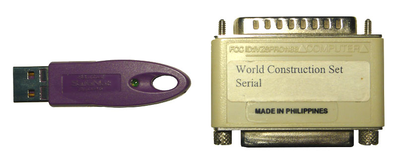
There are two types of keys currently available from 3D Nature: the beige parallel port and purple USB port keys. New USB keys shipped as of July 2007 will be mostly black with purple highlights near the SafeNet logo on the key. The exact text printed on the white label may vary, but it should say either 3D Nature, WCS/World Construction Set or VNS/Visual Nature Studio somewhere. The serial number is unique to each hardware key, though multiple seats purchased together or as additional seats may share the same serial number. You should not reveal your serial number to anyone except 3D Nature. In the event the paper adhesive label is missing, all 3D Nature keys bear the “SRB number” of SRB05967. The manufacturing code indicates the year and week the key was manufactured (0243 means 43rd week of 2002, 0504 indicates 4th week of 2005). In a situation where a hardware key appears to have failed completely, 3D Nature will probably need the manufacturing code to inquire with the manufacturer about any known defects in that manufacturing batch.
Effects, Links & Topology
VNS 2: While not technically a bug, this is a known limitation. The complexities of dealing with donut/island polygons don’t make it possible the way High-res Edge currently works. To smooth out the inner polygon effect, increase effect Resolution by manually decreasing the Resolution value in the Common section on the General page.
VNS 3 and later versions: VNS does not have the High-res edge setting because its internal effects system is always high-res. So, this problem never occurs.
The project’s vectors/polygons are most likely coming from a shapefile that was loaded with the ReImport When Project Loads option. These vectors (and therefore their component linkages) are discarded and not saved with the project, and a fresh set of the vectors is reloaded when the project is opened. This obviously breaks hard linkage.
Solution: Use dynamic linking via Search Queries or stop using ReImport (see “Turning off Dynamic ReImport of Shapefiles” in Support Knowledgebase: Shapefiles).
VNS understands the “hole” topology of multipart shapefile polygons and their proper winding order. Most vector-bounded area effects (like Ecosystems) will automatically obey these holes.
Foliage
Raster GIS data is available (often derived from LIDAR or RADAR data) that indicates canopy attributes such as height or density on a per-raster-cell basis. Usually this data is in the form of a 16-bit or 32-bit per cell/channel raster. Can VNS use this data? VNS currently only supports 8-bit-per channel raster image data (though some deeper raster data can be converted via the Import Wizard into DEM height).
Workaround: You could convert this to a raster image and use it as a texture to control the height of the vegetation. 8-bit texture images can only have 256 values (0…255 greyscale RGB values) so you would need to determine the maximum height and a scaling factor that will compress that range into 0…255. Then, tell the Ecosystem Editor to make the foliage the maximum height, and use the texture to specify where it should be scaled down and by how much. For example, say you have a 16-bit raster image, with values between 0 and 4572, representing canopy height in centimeters for a canopy of a maximum of 150 feet high. This 4572 number must be compressed down to 255. Determine the necessary scaling factor by dividing 4572 / 255 = 17.929. Use your raster GIS to calculate a new result from the original by dividing by 17.929. The new values will all be in the range of 0 to 255, and can be stored in a new 8-bit raster (preferrably a georeferenced GeoTIFF). Load the georeferenced image into VNS and verify its placement by temporarily using it as a simple Color Map. Once you have verified placement, disable the Color Map. In VNS, set up your ecosystem to have a maximum height of 150 ft or 4572 cm (VNS will take either unit). Create a Texture on the Height parameter, set the Element type to Planar Image, and choose the georeferenced image you already loaded. Now when VNS renders, values of 255 (white) in the image (which originally corresponded with the full 4572-cm height) will leave the specified height (150 ft or 4572 cm) unaltered. Areas in the image that are black (value of 0) will reduce the height to 0. Areas that are intermediate greys will scale the height linearly proportionally. The downside of compressing the data into an 8-bit raster is a loss of precision. in this case, the 17.929 factor (calculated from an original unit in centimeters) indicates that the data will be now be quantized into steps of 17.929cm (which is about 7 inches). This reduction of accuracy is usually not a significant problem for most users.
This is a side-effect of the fast and efficient method VNS uses to render huge quantities of foliage. In most flight paths the effect is negligible and not noticed. If you bank steeply (greater than 30 degrees) close to the ground in a vegetated area, it can be seen though. There is no real workaround. One possibility would be to render a non-banking path with a much wider camera FOV and larger rendered image size. This would allow you to perform an animated rotation of the finished animation and crop out only the desired portion of the view.
Lakes and streams have Beach materials that can specify vegetation both above and below the water surface. Vegetation placement can even react to water depth or height above waterline. Foliage placed by Foliage Effect can be manually dropped into submerged area and will stay in place. Foliage placed by other means (Ecosystem, Color Map match, Rules of Nature) will normally abandon its location if a lake, stream or ocean is placed to cover the area. However, to simulate temporary flood conditions, one can set a second “Reference Elevation” in the Beach Height section of the Lake component. This specifies the “long term dry” level of water, for use in determining where vegetation chooses to inhabit or not. Then, the actual Lake Elevation is presumed to be a temporary flood stage that will leave existing vegetation in-place but drowned by rising waters.
Forestry Edition/Wizard
The Forestry Wizard is designed to be self-explanatory, with detailed step-by-step instructions at each stage. There is no tutorial for the Forestry Wizard.
Projects rendered by the VNS 2 Forestry Edition have foliage placement that is somewhat different due to a more precise vegetation placement algorithm. They will not match non-FE renderings of the same project. Projects saved by the Forestry Edition are “marked” so that the Render Engine will know which algorithm to employ to render them. If you resave a FE project from a non-FE edition of VNS, it will alter this marking, resulting in the Render Engine using the wrong algorithm and the rendering not matching those made in the dongle-attached VNS Forestry Edition.
Solution: Only load/save FE projects from VNS running on an FE-authorized hardware key.
VNS 3 always uses the same higher-precision foliage placement code as VNS 2 Forestry Edition. VNS 3 also has other changes to the random number generators that make foliage arrangements different (neither better nor worse, just different) than any previous version of WCS or VNS.
Gridding & DEM Merging
Gridder components use a sort of mini Search Query for specifying which vector or point entities in the project should be used for creating the terrain skin. By default, this mini-query is set up to only look for “Control Point” type objects, either points or lines. However, shapefiles always import as “Vector” type objects, so the Gridder ignores them.
Solution: Multi-select the entities in the Database Editor and change their “Class” (on the Properties tab) from “Vector” to “Control Pts.” Alternately, in the Terrain Gridder Component editor (Current Filter tab), check the “Vectors” checkbox. However, this will make the Gridder consider ALL vectors, potentially including some (like vegetation boundaries, structure footprints, etc.) that you don’t want incorporated into the terrain skin.
Due to mathematical precision issues involving the small decimal values inherent in geographic coordinates, multi-res DEM merges do not work seamlessly. If you are doing multi-res merges, use or create a new system with a non-geographic method (UTM is fine) and use that as your output coordinate system.
Image Drapes & Color Maps
Configure the exporter to use multiple tiles. Google Earth isn’t too good handling single large images (like a 4000×4000 PNG) but it can usually handle a number of 512×512 images just fine.
Most remote-sensed images have shading and shadowing in them from when they were acquired, which is very hard to remove. VNS also shades them with the terrain relief and lighting conditions. This results in double lighting/shading.
Solution: Turn on “Luminous Colors” in the ColorMap Editor, or make the Material have 100% Luminosity if using it as a Texture. This will prevent VNS’s shading/shadowing.
In the grand priority scheme of VNS, Ground Components are about the lowest priority — they don’t cover anything and everything covers them. If you want to specify a vector-bounded landcover type that can override a Color Map, you should use an Ecosystem (without any EcoType foliage) instead of a Ground Component.
VNS only understand 8-bit-per-channel images. Some Pan or multispectral images are stored as 12- or 16-bits per channel. While this extra data is useful for analysis, it is not useful for visualization work as computer displays can only display 8 bits of data per channel anyway.
Solution: Use a raster GIS (or a processing tool like Global Mapper to convert the 16-bit image down to 8-bit per channel.
“I want to tint vector-controlled regions so that they indicate an area without obscuring the draped image underneath.”
Solution: If you’re using a Color Map to drape the image, you’ve already discovered that Ground Components can’t cover Color Maps and Ecosystems supersede Color Maps leaving no trace of the drape image. Two options are available to you: Vector-bounded Snow components (with wide-open slope/elevation/etc Rules of Nature) can be set to have partial transparency. They are mixed in over the top of whatever the underlying layer is (including Color Maps). Another alternative is to use Ecosystems, each with a proper Diffuse Color, but add a Texture to the Diffuse Color utilizing the Planar Image element type with your georeferenced image. The Opacity of the Planar Image element can be turned down (to say 50%) which will show through some of the plain Diffuse Color you specified.
Sometimes when loading a georeferenced TIFF (that is not an actual GeoTIFF), the image does not get placed in the proper location. A real “GeoTIFF” has all of the coordinates and projection information (and importantly, units) stored in the .TIF file, and does not need a TFW Worldfile. A TIFF with a worldfile is less informative because it doesn’t have the projection or units info, all it has are the actual coordinates. Sometimes the projection information is stored in an accompanying .PRJ file, but even this may not store the Units information. As an example, the TIFF and TFW may be intended for use with the NAD_1927_StatePlane_Colorado_Central_FIPS_0502 system. This projection uses units of “US Survey Foot” — a measurement similar to, but slightly different from the common foot. VNS assumes meters when it cannot find any indication of what units it should use. So, it’s misinterpreting your US Survey Feet as meters, which ends up placing your image in the wrong place.
Solution: Probably the easiest way to correct this (without having a real GeoTIFF which would tell our software what units to use) would be to alter the TFW file. Here is info about what a TFW file is made of: http://duff.ess.washington.edu/data/raster/drg/tfw.html. The first and fourth lines are the size of a pixel and the last two are the coordinates of the upper-left corner of the image. You can take each of these numbers and multiply them by .304800609601219, which is the conversion factor between US Survey Feet and meters. Resave the TFW file and then remove and re-add the TIFF image in VNS. The image should position itself at the proper location.
Image Management
Due to the block-compressed nature of JPEG images, decompressing a small region of an image without decompressing all of the image up to that point is not possible. Therefore, it is very poorly suited for Image Management use, running quite slowly. Rather than just prohibiting this usage, we left the ability in case you have no other choice. However, converting the images to GeoTIFF (hopefully tiled GeoTIFF) will greatly increase the speed.
Lights & Shadows
Is your DEM located at the correct position in the world? If it is not, all global calculations (like sun position) will be wrong. A few locations use non-regular time zones. In these situations, you must determine what the proper local time should be and use that rather than the actual local time. Or, use a reference longitude of 0, and enter the “local” time as the equivalent GMT (Greenwich Mean Time or “Zulu” Time). Set Sun Position by Time also does not adjust for Daylight Saving Time. During the summer DST months, enter the non-DST time (which is normally one hour later).
If you use Variable Fractal Depth, the Level of detail calculations could be different when the shadows are calculated than when the rendering is done.
Solution: Use Fractal Depth Maps when working with shadows.
VNS use shadowmaps instead of ray-traced shadows, because ray-tracing is impractical on massive scenes. Shadow Maps consume large amounts of memory, and therefore steps must be taken to reduce their memory footprint. One compromise is to use 32-bit (4-byte per shadow cell/pixel) single-precision floating point numbers to store the shadow surface distance rather than the full 64-bit (8-byte) values. The downside of this is that shadow maps sometimes are “fuzzy” about whether a surface is behind a shadow-casting surface or not. Sometimes the shadow system confusingly believes that a surface is behind a shadow-caster when in fact it is itself the shadow caster, and can’t possibly be behind it.
Solution: Shadow Maps use a compensation factor called “Shadow Offset.” This appears as the “Shadow Offset from Terrain” control in the Cast Shadows tab of the Shadow Editor. Adjusting this higher will prevent the stippling. Stored Shadowmap Files on disk do not need to be regenerated when this value is changed, so you can easily experiment with it to see how high it needs to be. Setting this value too high will result in shadows that no longer appear to “attach” to the base of the item casting the shadow. This is particularly visible with trees and flagpoles. Sometimes it may be necessary to use a large-area shadow with one setting, and one or more small-area shadows with a different setting to properly capture features of this type.
Shadow Offset is too high. See “Shadows have weird artifacts — usually triangle stippling” for a discussion of this value and how to tune it.
Memory and Errors
http://msdn.microsoft.com/en-us/library/aa384274(VS.85).aspx
http://support.microsoft.com/kb/833721
Current versions of VNS are compiled with the “LARGE ADDRESS AWARE” setting, and thus if Windows is also configured for it, will have access to more memory (usually 3Gb). Instructions for configuring 32-bit Windows (2000, XP) are in the Microsoft page above. 64-bit versions of Windows XP and later also recognize this flag, and can provide VNS 4Gb of address space.
This indicates that a portion of the project file has become corrupt. VNS may or may not have loaded some parts of your project. A chunk size error indicates a misunderstanding between the file saver and loader. The saver saved something that the loader couldn’t understand. Fortunately, VNS files are divided into Chunks by category, so Images are in one chunk, Components another, Database is another, etc. So, if one chunk is unreadable, the others still can be recovered. If it’s the database chunk that is getting munged, you might take a step back and look at your database and its usage in the project. If there’s something you are doing differently that usual, it could be provoking an uncommon error that then makes the saving of the database chunk unsuccessful.
Recovering Chunks: The contents of the database can sometimes be recovered using the Load button in the Database Editor and feeding it the .proj file. Likewise, in the Component Library (not Gallery!) there is a New File… button on the right half that will allow you to select a .proj file and load an overview into the right hand list. From here you can select one or more components to copy into the current project.
Effects Memory is used by Components attached to vectors at render time. VNS sets it aside from your computer’s available RAM. An error means the render is demanding more memory than you have set aside. It could be one hi-res effect covering a very large area, or it could be a lot of widely-spread low-res effects. Increase Maximum Effect Memory in the Component Library for starters. If you run out, start reducing the Resolution of vector-based Components. There’s no problem setting the value high; VNS won’t use the memory unless it needs it. This topic is visited in detail in the Roads section of Getting to Know VNS 2: GIS Applications.
This usually follows an error initializing effects (see “Error initializing Effects” above), but also occurs when importing a DEM that requires more RAM (physical and virtual) than you have. Adding RAM and increasing virtual memory probably won’t do you any good. Windows does not allow any program to use more than 2 Gb of RAM (with some exceptions, see the “/3Gb Windows option” above). If it’s not a DEM import, anything you can do to reduce RAM use will help:
-Increase Effect Resolution values wherever you find them. The Status Log lists memory usage amount during rendering.
-For large images, render in segments (don’t forget to add plenty of Bottom Overscan)
-Reduce Pixel Fragments value or disable.
-Disable Render Diagnostic Data on the Render Options Editor>Enabled 2 page.
“…This may cause excessive memory usage. Consider tiling DEMs.”
VNS ran out of memory during rendering. Specialized code noticed that you had some DEMs in your project that were larger than VNS’s recommended tile size. This can cause higher (sometimes MUCH higher) than normal memory consumption. VNS recommends that you tile your DEMs for more efficient rendering (see “Tiling DEMs for more efficient rendering” in Support Knowledgebase: Data Import).
VNS stores a lot of extra data with every rendered pixel. Most other renderers only need to store the RGB color once they have completed a pixel, but our large-scene-paging rendering method means we need to store more information in case some later part of the scene gets rendered into the same spot and needs to be integrated into the same pixel. As a result, when rendering very large images, you can run out of memory.
Solutions: One option is to use Segments or Tiles. The Render Options allows you to chop up the rendering into smaller pieces which will be reassembled into one image automatically when rendering is complete. Segments (and to a lesser extent, tiles) have side effects relating to reflections and may require more overscan (see “Reflections look bad when using Segments, in certain scene compositions, or below 3D objects” in Support Knowledgebase: Rendering). A second option is to switch to the older, lower-quality non-Pixel-Fragments rendering algorithm. This method does not handle reflections and transparent objects (glass) as well, nor does it do as good of a job of anti-aliasing. However, it is often adequate for the types of cartographic work that often calls for very large renderings. Disable Pixel Fragments by unchecking “Fragments Enabled” in the Render Quality section of the Misc tab of the Render Options.
Monitor the amount of Effects Memory in use for each category of vector-bounded Component by examining the output in the Status Log after each render. Look for categories that consume a lot more memory than others, and try to minimize the consumption.
Don’t use higher-res effects than needed. If you just need crisper edges, try a lower resolution and turn on hi-res edges. This doesn’t really help for Effects with Cross-Section or Edge-Feathering Profiles — those just plain need higher resolution.
Freeze any large/coarse Terraffectors permanently into the DEM. Finer-detailed Terraffectors and Linear Terraffectors that also perform ecosystem-assignment by profile segment are not eligible for this.
Reduce the area covered by vector-bounded effects, if it is large and/or their resolution is finely-detailed. If you have vector-bounded effects that are spread our sparsely, the regions in between vectors still consumes just as much memory. Consider freezing coarse or far-off Terraffectors to reduce the contained area that the Effects subsystem must calculate at render-time.
If you have a long flight-path that passes over a large area full of detailed vector-bounded effects, consider breaking the animation up into shorter segments that are rendered independently and assembled back together when finished. VNS’s Scenarios can be used to manually disable Vectors/Components that correspond to effects that you know won’t be visible to the camera during certain times, allowing you to reduce the region-of-effect area. Once the scenarios are set up, they can be added to the render job for each animation segment to ensure everything is automatically switched on and off properly.
Make sure your DEMs are tiled to nominally 300×300 to 500×500. Bigger DEMs take a bigger bite of RAM during processing.
Turn off “Render Diagnostic Data” when you don’t need it. A few exotic PostProcess effects might need it, but most of the time you won’t need it in final renders.
Use Segments or Tiles when rendering large output images. Make sure to use Overscan to ensure trees don’t drop out.
Don’t render a higher resolution than you really need. For print work, figure out the size it will be printed at, the distance it should be viewed from, and work out the minimum DPI (and therefore image pixel dimensions) needed for proper detail. Large posters don’t usually need to be 300DPI.
This error indicates that a polygon or collection of polygons together created a piece of geometry with topology that VNS 3 couldn’t make any sense out of. This could result from polygons that have duplicated points, polygons with interior (“negative space”) regions that cross over the exterior boundary, polygons that crisscross themselves, or other nonsensical shapes. VNS 2 utilized a crude approximation technique that wall-papered over many polygon data defects, but VNS 3’s higher-quality results demand higher-quality input data. VNS 3 does try to fix certain basic problems for you silently, and if it is successful, you’ll never see an error or even know there was a problem. This error only occurs when VNS 3 is faced with an error it can’t figure out how to fix.
Troubleshooting an error like this involves identifying the polygon(s) to blame, and then examining them for problems and defects. Due to the complex processing that VNS 3 does to the polygon dataset, it is not possible for us to tell you exactly which polygon(s) are to blame by the time we determine there is a problem. The dataset has been sliced, diced and mangled in so many ways that it only resembles the original data in shape — the form and organization has been completely altered irreversibly. The best way, then, is to use a process of elimination to determine which polygons it is NOT. You could go through every polygon in your database (that is linked to a component) and enable and disable them. For small projects maybe this is practical. However, usually you will want to do some more extensive elimination first.
The easiest way to eliminate large numbers of polygons is by effect/component type. Look at each type of vector-linked effect or component, and turn them off one by one. When the problem disappears, you know which effect type is responsible and can then examine things more carefully. Typical vector-linked components are going to be things like Roads, Ecosystems, Streams, Lakes and Walls. Vector-linked components like Foliage effects are not likely to be the cause, nor are 3D Objects. Components like Sky, Camera, and Atmosphere do not have any vectors linked to them, and cannot be the culprit. So, one component category at a time, disable all the components in the category. Once the error goes away, you will know what category the problematic vector is linked to. Now, narrow it down to a single component by enabling each Component in that category and watching for the reappearance of the error.
Once you know which Component is responsible, follow a similar process of elimination by enabling and disabling the vectors attached to the Component to identify the actual vector(s) at fault. Remember, just because you find ONE vector that has a problem doesn’t mean the entire problem is solved — you may have more than one troublemaker, complicating your process of elimination. Once you have found the problem vector, the actual cause is usually pretty obvious in the form or wild and crazy vector geometry or messed-up topology. However, if the cause isn’t obvious, you can contact us for further advice.
Nature View
If the NVW scene text file is hand-edited, NatureView will no longer accept and load it. It must be re-signed. From within VNS with Scene Express, select the Sign NatureView File… item from the “Scene Express Utilities” sub menu under the “Data” menu. From the file requester, choose your modified .NVW file. VNS will update the signature at the end of the NVW file to make it acceptable to NatureView.
To keep the size of the NatureView viewer down, and improve performance, NatureView does not have a built-in coordinate system and datum reprojection engine. So, NatureView only works with data in Geographic (lat/lon) coordinates internally. Fortunately, VNS has automatic projection/datum conversion built in. In VNS, simply create a new coordinate system (or choose an existing system) that is Geographic (not UTM, or State Plane or the like). You can use any Datum/Ellipsoid you wish. Reprojecting it into NatureView’s geographic system will not harm or degrade your data in any way. This system (and datum) will also be the basis for all the lat/lon coordinate readouts shown in NatureView.
In the Advanced settings for the NatureView format (Scene Exporter), there is a setting that limits the maximum number of trees displayed (for safety, to not overwhelm and kill slow graphics systems). This defaults to a low number, but you can increase it as much as you want. All the foliage is exported to the NatureView file no matter what this setting says, so the foliage display limit can simply be changed in the already exported NVW text file without having to re-export. The NVW file will need to be re-signed for NatureView to accept it (see “Re-Signing a NatureView NVW scene file” above).
Projects & Project Files
VNS only has limited undo. Users make changes they sometimes regret. Occasional program errors and corrupt input data sometimes cause crashes or damage project files. 3D Nature recommends resaving the project (via Save As…) under a new name (such as MyProject_1.proj, MyProject_2.proj, MyProject_3.proj, etc) periodically. This allows you to recover from errors, as well as revisit previous incarnations to compare results, techniques or discarded work.
To solve the problem you will need to determine what aspect of the project is crashing. This is a process of elimination. A good path to follow is to categorically disable suspected portions of your project, and see if it makes the crash go away. Once a category is identified, can you pin it down to a particular item in the category? If so, you can examine the settings for that item and look for unusual differences that might provoke the failure. For example, try going through each of the major Task Modes, and disable all the Components of a particular type: Ecosystems, 3D Objects, Terraffectors, Lakes, Clouds etc. If disabling a category doesn’t fix the problem, reload the unaltered project and try again. If you narrow it down to, for example, 3D Objects, then reload the project and turn off each 3D Object individually to see if you can isolate a single culprit.
Keep in mind that there may be more than one bad guy. Some more things to consider to help pin down the cause of the problem (and therefore resolve it): Does it happen all the time? Does it happen in all projects? Does it happen or can it be replicated in a supplied demo project? Did it just start happening? If so, what events have happened recently that it might be connected to? Does it happen in an earlier version of your project? What has changed in the interim? Did it appear when the software was updated? Do you still have the older release of the software? Can you confirm it works as expected in the older release?
Rendering
Turn on Render Beyond Horizon, a large-project optimization setting found in the Misc tab of the Camera.
Turn on “Safe Mode (GDI Only)” in Quicktime’s “Preferences>Advanced.”
Make sure when you generate Fractal Depth Maps that you don’t use too high of a frame interval. If a DEM only becomes briefly visible during the frame gap falling between the frame interval you used in FDM creation, it will be not be marked as used, and won’t show up in the animation (even if it does come into view).
If you don’t want ANY vectors at all showing up, you can uncheck the “Render Vectors” checkbox in the Vectors section of the Misc tab in the appropriate Render Options. If you only want to inhibit the rendering of certain vectors, open the Database Editor, multi-select the vectors in question, and uncheck the Render checkbox below the Label field.
This is part of VNS’s specialized “2.5D” shading technique to make flat tree photos look more 3D and respond to lighting as if they were non-flat. You can turn off this effect in the foliage with the Apply 3D Shading checkbox in the Objects tab of any foliage editor (Foliage Effect Editor, EcoType [VNS 2] or Ecosystem/Stream/Lake [VNS 3] Editor). Similarly, Random Flip X should be off for any asymmetrical non-foliage images or non-foliage images with text in them.
“In a project that uses hundreds of 3D Objects, rendering is very slow.”
The usually-unstated criteria here is that the 3D Objects (3DO) are set to Relative to Ground mode, and there are probably Terraffectors (linear or area) in the project. Each 3D Object, if it is in relative-to-terrain mode, must analyze every Terraffector in the project to see if it affects the elevation of the terrain under the 3DO anchor point, since the 3DO height will be affected by terrain height changes. Evaluating Terraffectors as part of the normal terrain rendering procedure is a more efficient process than this piecemeal approach. In many cases, the Terraffectors may not even influence the 3D Object height at all, but the program can’t know that without checking them all.
Solution: If possible, conform all of the 3DO-attachment vectors to the terrain, and then change the 3DOs to relative-to-vector mode, not relative to ground. This should eliminate the Terraffector evaluation that is bottlenecking the render process.
Vectors travel a straight line between each of their vertices. If the terrain undulates along this path, the vector could dive straight through the terrain and become obscured.
Solution: In the Render Options component, Misc tab, Vectors section, increase the value in the “Z Offset” field. This will artificially treat vectors as if they were that much closer to the camera when determining occlusion. It will not actually change the location/height of the vector, it will simply bias in favor of the vector when comparing if it or the terrain is closer during visibility calculations. An alternative is to densify the vector to have more vertices using the Vector Editor, ensuring that you reconform the vector to the terrain after increasing the number of vertices in it (see “Can I increase/decrease the number of points in an existing vector, or smooth it?” and “How do I make a vector follow a DEM model’s surface?” in Support Knowledgebase: Vectors).
The efficient reflection algorithm invented for VNS traces reflection ray intersections against the finished pixels in the rendered image rather than against the scene geometry (as other ray-tracers would). What this means is that VNS can only reflect things that appear in the rendered scene. When using Segments, the rendered scene is comprised only of the Segment being rendered — not the rest of the finished image.
Solutions: VNS render tiles offer some help — reflections usually only reflect things above them in the rendered image, so dividing the image into tall thin strips (X tiles=several, Y tiles=1) instead of the X tiles=1 Y tiles=many arrangement of Segments works better. Certain scene compositions (like, all water, no shoreline or sky visible) will leave VNS unable to find anything interesting to reflect, and only basic sky color will be used. If you have problems with reflections when looking under a bridge or other overhanging 3D Object structure, it is because the bridge obscured the desired reflection data in the finished image. Checking “Render Occluded” in the 3D Object Editor>General tab of each 3D Object in this sort of situation will instruct VNS to preserve the occluded imagery behind the object in a “deep” form that will allow it to be accessed for reflections. This setting consumes more memory, so only employ it where needed.
While the overall UI in VNS responds to the frames versus time preference set in the Preferences/Units window, the frame rate used in the Render Options window can be different from that elsewhere in the program. Each Render Options specifies its own frame rate, allowing one project to be rigged to create output for film (24fps), NTSC video (29.99 or 30fps), PAL video (25fps) or a variety of other playback rates. When specifying times in frames in the Start and End Time fields, the frame rate of the Render Options is used to interpret these into decimal time (which is what VNS stores and uses internally). This can cause confusion if it does not match the frame rate specified in the Preferences/Units window and used/displayed everywhere else in the program.
PostProcess Events that rely on something specifically positioned on the rendering (Image Overlay, Text Overlay) do not work properly when rendering with segments or tiles. In segmented/tiled rendering, VNS believes the segment or tile to be “the whole rendering” and will mis-position or scale the overlay to fit only the current segment or tile. This will be done for each segment/tile, resulting in the overlay repeating over all.
Solution: Either avoid text/image overlay when using segments/tiles, or save the unprocessed images to an image sequence, then set up an empty project that loads the rendered images as a background with the desired text/image overlay, and render this without using segments/tiles.
Assuming you’re not mastering a DVD or video tape (which is a whole different process) you will need to make an AVI/WMV, Quicktime MOV or similar animation file to send to your recipient to view. Various file formats and codecs have wildly different size/quality tradeoffs and minimum playback system requirements. In this era, most desktop and laptop computers are powerful enough to play back high-quality compressed video of at least 640×480 size.
3D Nature users and experts have contributed their evaluations of the best choices for this situation. These suggestions are considered best practices as of March 2007.
AVI: No standard Windows XP codec (one that comes with Media Player) yields animation quality that is considered usable. Add-on codecs were not tested because clients typically are not able or willing to install new software. AVI is not known for its portability or playability on Mac systems.
DivX was not evaluated due to the high amount of spyware installers associated with this format.
WMV: This was a surprise entry in last year’s competition. The WMP9 encoder is a free download and the WMVs it creates are compact and of surprisingly good quality, comparable to MOVs. Results are far better than any of the standard AVI codecs for animation.
MOV: This continues to provide the best quality bang-for-MB-buck. MPEG-4 gives good quality and compact files. H.264 gives very good quality at higher file sizes. Both can be played back on the current Quicktime player, which nearly everyone already has installed on both Windows and MacOS.
Increase either Vertical or Horizontal Overscan (respectively) in the Size & Range tab of the Render Options in use. Refer to the Online Help for an explanation of how these factors affect your rendering. These factors are especially important when rendering with Segments or Tiles.
Use Fractal Depth Maps instead of Variable Fractal Depth. VNS strongly warns you to avoid Variable Fractal Depth in an animation. Listen to it.
“2.5D” Billboard trees such as VNS typically uses, always face directly towards the camera. This is to prevent them from becoming thinner and thinner and eventually being paper-thin when viewed from above. However, as a side-effect, they may stick “into” a hillside when viewed from above on terrain of high-relief. To prevent this, turn on Render from Overhead in the “Foliage Z Offset” section of the Misc tab of the Render Options. Do NOT use this option unless you are rendering overhead-looking-down views, as it will have other side effects (such as trees being visible through hills or other objects that ought to obscure them). Read the description in the Render Options as well as in the online help for more details.
See “Why does vegetation disappear on some slopes when viewed from an Overhead or Planimetric Camera?” elsewhere in this section.
Scenarios
VNS 3 Scenarios have been enhanced to allow some controlled items to be “negated” — and will be set to the state opposite of the main Scenario. This makes it much easier to set up projects using Scenarios, sometimes cutting the number of Scenarios needed in half.
VNS 2: A single Scenario can only turn its controlled items on OR off. It cannot turn some on and some off in one operation. Typically, when using Scenarios, you will construct them in pairs: “Scenario A On” and “Scenario A Off.” Put all the items that must be present for Scenario A into the “A On” and likewise all the items that must not be present for A into “A Off.” Set the enabled state control for each to “On” or “Off” respectively. You will add and run both the On and Off Scenarios to a Render Job, as both are necessary to establish the proper state of all items to represent the “A” state. If the Scenarios are animated, the On/Off state of one will be the exact opposite of the other.
Scene Express
Configure the exporter to use multiple tiles. Google Earth isn’t too good handling single large images (like a 4000×4000 PNG) but it can usually handle a number of 512×512 images just fine.
VNS: Google Earth export currently requires the Scene Exporter be set to use a Geographic WGS84 Coordinate system. Some lingering coordinate transform issues remain though, and it is sometimes necessary to set your Project Default Coordinate System (in the Planet Options) to a WGS84 system. This may affect the position of Cameras in the project.
WCS: WCS cannot do reprojection or datum conversion, so alignment within Google Earth will only be correct if all of the input is in a geographic WGS84 system (or the nearly-identical NAD83).
Google Earth terrain export, while supported by Scene Express, has many limitations. Google Earth doesn’t technically allow for the over-riding of their built-in terrain model, so Scene Express builds a color-textured 3D object representing the exported terrain and inserts it into Google Earth at the proper location.
However, Google Earth is very sluggish to handle large, detailed 3D models like these, so performance may be poor. In addition, there is no way for this model to prevent the original terrain from showing. This means that the exported terrain model is good for depicting features (like mountains — https://3dnature.com/index.php/products/scene-express-2/scene-samples/: see Google Earth 4 Red Rocks LIDAR and Google Earth 4 Matterhorn) that stick up higher than the Google terrain, but cannot properly depict features like quarries that must cut below the original terrain model.
In the Advanced settings for the NatureView format, there is a setting that limits the maximum number of trees displayed (for safety, to not overwhelm and kill slow graphics systems). This defaults to a low number, but you can increase it as much as you want. All the foliage is exported to the NatureView file no matter what this setting says, so the foliage display limit can simply be changed in the already exported NVW text file without having to re-export. The NVW file will need to be re-signed for NatureView to accept it (see “Re-Signing a NatureView NVW scene file” above).
Search Queries
Setting up multiple criteria within one Filter within a Search Query results in a query of (a AND b) as opposed to (a OR b). Essentially, ALL criteria within the filter must be met for the selection to pass the filter. To implement an OR functionality, use two consecutive filters, one with the ‘a’ criteria and one with the ‘b’ criteria.
Create one filter with the “Add Objects” radio button selected. Set up the ‘a’ criteria in this filter. Create a second filter with the “Subtract Objects” radio button selected, and make sure it is below the first in the Filters list. Set up this filter with the ‘b’ criteria. Objects that pass the ‘a’ filter and are added to the selection set will be removed if they pass the ‘b’ criteria.
Shapefiles
Sometimes a shapefile is imported with “Reimport When Project Loads” but later it is determined that this option is not desired. Dynamic ReImport is considered to be a “Template” feature and is controlled through the Template Manager.
Open the Template Manager from the “File/Template Manager…” menu item. The lower half of the window shows “Auto Import Operators.” Any ReImport shapefiles will be listed here. To make a ReImport shapefile become a part of the project and database, saved each time with the project, select the corresponding item in the list, check “Embed Auto-Import Operator’s Components in Project” and click “Apply Changes.” To remove a ReImport shapefile entirely, select the corresponding item in the list, check “Remove Auto-Import Operator from Project Permanently” and click “Apply Changes.”
“… which keeps restoring them to un-conformed.”
In the Import Wizard settings for shapefiles, the final page has a group of checkboxes one of which is “Conform to Terrain.” Choosing this will tell the Import Wizard to conform automatically after loading, which it will do during every ReImport.
“Changes I make to my shapefile vectors (moving, deleting, editing, altering attributes) don’t seem to “stick” after I reload my project.”
You probably turned on ReImport on Load in the Import Wizard when you first imported the shapefile. This causes VNS to not save a copy of the shapefile’s contents, but rather, reload a fresh copy each time you load the VNS project. You need to turn off ReImport (see “Turning off Dynamic ReImport of Shapefiles”).
It is not possible to import the symbology definitions from a shapefile into VNS, because the shapefile format (which is what VNS understand how to import) doesn’t actually store any of that information. As a workaround, if you need to depict cartographic features such as these in a VNS landscape, you might consider exporting a large georeferenced (GeoTIFF) image from ArcGIS with the features you want rasterized into it, and drape that in VNS.
Templates
Templates are a very advanced and tricky feature, and come with many caveats. When templates have components that utilize images (for textures or foliage images, usually), those images are stored in a list within the template and the components refer to the image by image number. If a project is created using the template, and then the template is modified to use new images, the ordering of the images in the list can change. This can cause a disparity between what image number the project thinks it needs and what number the image actually is now in the template file’s list. This problem cannot be worked around due to the nature of templates. Once you begin using a Template, you should exercise extreme care in altering the template’s use of images in any way.
Terraffectors
The mathematics of Terraffectors do not currently permit this. However, a “Revert” (linear) Terraffector is included in the Component Gallery that can be applied to a second vector slicing off the end of the road to accomplish this. See the Revert Component description in the Component Gallery. (An Area Terraffector version of Revert is also included.)
Within the Ecosystem component (which Road Terraffectors typically employ to specify the asphalt appearance) in the Miscellaneous section (oddly, on the Color Map tab of the Ecosystem Editor) there is a “Snow Cannot Cover this Ecosystem” checkbox. Turn it on.
The UrbanParkStudy demo project included with VNS was designed to demonstrate and illustrate the principles necessary to accomplish this. Examine, copy, modify and reuse the components used in this project. Observe the Priority and Evaluation Order of the various Terraffector components — with the exception of Urban Street Stripe Eraser, they are all the same, 0 and 1 respectively. All of the precedence is determined by the Priority on each segment within each Terraffector component’s Profile. Higher priorities supersede lower-priority segments on the same or other Terraffectors. You may find it useful to make a chart of all the different terraffector types you will require and diagram the priorities of every segment before constructing the project.
“Can I control the color, texture or vegetation within an Area Terraffector the way I can with the Profile Ecosystems of a Linear Terraffector?”
No, and Yes. While the Area Terraffector itself has no similar control, the same result is accomplished by simply creating an Ecosystem component with the desired appearance, and attaching it to the same vector the Area Terraffector uses.
Texturing
Textures for components like Terraffector roads (striping, pavement ruts) or Wall Panels (building side textures) need to have their Coordinate Space (in the Size & Position section of the Texture Editor) set to Vector Aligned. Otherwise the texture will not properly track, follow, wrap and align as the controlling vector twists and turns.
See “Textures on Vector-Aligned effects usually must also be Vector-Aligned” above.
User Interface
Make sure the window in question is actually open by looking in the Window menu. If it appears in the Window menu, try selecting the item in the Window menu to bring the named window to the front if it is hiding behind another window. If this still does not reveal it, it may be open, but have somehow been moved offscreen where it is not visible. If you cannot locate where the window might be obscured, you can make VNS forget all of its remembered window positions by deleting the preferences file:
1. Exit VNS.
2. Locate the VNS.prefs file in the WCS directory, the same place where your VNS.exe file is.
3. Delete the .prefs file.
4. Start VNS. You will be prompted to identify where your WCSFrames, WCSContent and WCSProjects directories are, since these are remembered in the same prefs file you just deleted.
Vectors
The “Set Attribute Value” button in the VNS Database Editor supports several useful “special” values in VNS 2. These values are interpreted functions rather than constant values, and they allow you to calculate a number of useful numbers on many vectors at once. The currently-recognized special values are: *calcmax *calcmin *calcavg *calclen *calcarea *calcrand. Max, Min and Avg will calculate the maximum, minimum or average elevation (in meters) of the vertices of the vector in question. Len will calculate length (in kilometers) of the vector. Area will calculate area (in hectares, I believe). Rand will calculate an integer between 0 and 10.
To use these features, you must already have an existing, numeric attribute on all the vectors you wish to use it on. If you do not have such an attribute, select the vectors in the Database Editor and hit the “Add” button on the Attrib tab of the Database Editor. Give the attribute a name, and for a value, enter 0 (so it will be created as a numeric attribute). Now, make sure your newly-created attribute is the one selected in the attribute list, and hit the “Set Attribute Value…” button. For the value, enter one of the *calc strings above, with the leading * and all. When you hit ok, VNS will calculate the value in question for each vector and store the result in the specified attribute. As another user pointed out, if you wish you can now Conform the vectors to the attribute value. This allows you to set an entire vector’s elevation to be the maximum, minimum or average, en-masse. (This only is useful if your vector already HAS elevation values, or has been conformed to terrain to give it elevation values.)
If you don’t want ANY vectors at all showing up, you can uncheck the “Render Vectors” checkbox in the Vectors section of the Misc tab in the appropriate Render Options. If you only want to inhibit the rendering of certain vectors, open the Database Editor, multi-select the vectors in question, and uncheck the Render checkbox below the Label field.
Yes. The Vector Editor has tools on the Point Operations tab for changing the number of points. Likewise, the Smooth tab offers the ability to smooth and re-space vertices in any or all three axes by a defined amount.
The Extent tab of the Database Editor offers tools for merging one or more vectors together, as well as splitting a vector into two at a defined point.
The Conform button in the Extents tab of the Database Editor (when employed with “Terrain” selected in the adjacent To: field) will make the vectors conform to the terrain surface. The conform elevation is only calculated at the existing vertices in the vector. A long straight segment of vector could therefore plow right through a hill or mountain if there were no vertices in the middle of the segment. You can increase the number of points in the vector and re-conform to solve this (see “Can I increase/decrease the number of points in an existing vector, or smooth it?” and “How do I make a vector follow a DEM model’s surface?” above).
Views
Number one first thing to do when experiencing odd visuals in a View is to ensure you have the most up-to-date drivers for your graphics card. Start at the graphics chip manufacturer official website.
Official Sites:
http://support.amd.com/en-us/download Main AMD Drivers Page
http://www.nvidia.com/content/drivers/drivers.asp NVidia Official Driver Page
OpenGL has a limited dynamic range for z-values (called “hither” or “near” and “yon” or “far”). If you have data (DEMs or vectors) that is both near and very far away, this can expand the range that VNS needs to encompass to be quite large. If the “near” clip distance is close to the camera and the far is quite a ways away, artifacts can appear in the View where it has trouble distinguishing which objects are in front of others. To avert this, as the far distance increases, the near clip distance is automatically pushed back somewhat. This only affects realtime Views, not renderings. Usually far-distant data like this is a anomaly. In VNS you might try to do a Search Query that grabs all enabled DEMs and Vectors that lie at least partially outside the area you expect your data to be. If anything is found by the SQ, analyze if it is valid (could be a stray vector from someone’s sloppy CAD work), and disable or remove from project if it is invalid.
Walls
Wall components are made precisely for lofting geospatial outlines into 3D structure representations. If available, GIS attributes such as number of floors or height (above ground, or absolute elevation) can be linked through Thematic Maps to automatically extrude the building masses to the proper height.
Use transparency on the Wall Panel material to make non-opaque areas.
Water: Lakes & Streams
The project involves numerous lakes, all specified by a GIS polygon outline. Lake surface elevation data may not be available. If the lake polygons are 2D shapefiles, conform them to the terrain in the Database Editor. Dig lake beds using a single Area Terraffector operating in Relative mode with an edge feathering profile and a negative elevation change. Since the actual lake depth is probably unknown, choosing a plausible depth (say, -5 m, or about 15 ft) is important.
VNS 3 Solution: VNS 3 has a Smart Lakes feature that allows you to specify the water level as relative to the containing vector’s elevation. It performs the equivalent of the VNS 2 steps below for you.
VNS 2 Solution: Use the *calcmax or *calcmin technique to determine a plausible lake surface elevation for each lake vector and assign it to an attribute (see “Undocumented: Attribute (elevation/length/area/random) Calculation” in Support Knowledgebase: Vectors). Create a single Lake Component and use a Thematic map on the Lake elevation, driven from the attribute value you just calculated.
Lakes and streams have Beach materials that can specify vegetation both above and below the water surface. Vegetation placement can even react to water depth or height above waterline. Foliage placed by Foliage Effect can be manually dropped into submerged area and will stay in place. Foliage placed by other means (Ecosystem, Color Map match, Rules of Nature) will normally abandon its location if a lake, stream or ocean is placed to cover the area. However, to simulate temporary flood conditions, one can set a second “Reference Elevation” in the Beach Height section of the Lake component. This specifies the “long term dry” level of water, for use in determining where vegetation chooses to inhabit or not. Then, the actual Lake Elevation is presumed to be a temporary flood stage that will leave existing vegetation in-place but drowned by rising waters.
“How do I visualize a complex flooding event where water moves across the landscape in non-constant elevation streams and fills low-lying areas at different times and rates?”
The problem is that this is a complex water transport scenario, and VNS is not a hydrology simulator. If you happen to have a hydrologic model or modeling tool, you could probably use the output from it to feed VNS.
Solution
You can control the height of the water surface in a limited sense using a raster image drape (similar to a Color Map) that can potentially involve several images representing different stages of the flood over time. Create one Lake, and make it go everywhere that will eventually need to be flooded. Determine the difference between the lowest elevation in that region that will be unflooded at the start, and the highest floodwater elevation at maximum flood stage. This will be your flood elevation range. Set the Lake Elevation to the low value of the elevation range. On the Waves sub-tab of the Water Mat’l (Material) tab of your Lake, set the Added Roughness field to the positive difference (in meters) between your low and high range values. At this point, if you rendered, you would be at full-flood-stage everywhere.
Create one or more georeferenced greyscale raster images that specify, in black-to-white, how much of that flood should be where at a particular stage. Your first stage image might be mostly black everywhere, with a few dark-grey regions elevating the water level just outside the dikes. In the next stage these fingers could reach outward and begin to fill low-lying areas. Later, whole regions will be filled with a solid (grey) color indicating that the water had reached an equilibrium level there. You will apply this as a Texture using the Planar Image element to the Added Roughness control. You can either use a single Planar Image element, accessing a (georeferenced) image in the Image Object Library and set up a Sequence/Dissolve to cycle through your set of images at a fixed rate.
Or, if you want more control over non-regular timing, stack up a bunch of Planar Image elements, with the earliest being on top. Animated dissolving out the Opacity of each one to reveal the one below at the proper time. The precision of elevation control offered by this technique is ElevationRange/255. So, if your elevation range of the flood water is 10 m, each step of grey in the drape image represents .039 m (or about 4 cm) of water level change. This is usually plenty accurate given the poor accuracy of most terrain models. You may wish to have VNS output a georeferenced base image (render a Projected Planimetric Camera and save a TIFF with a worldfile) that you can use as a reference while painting the flood progression. You might also wish to similarly export the ELEVATION channel to a georeferenced TIFF to use as a elevation reference for placing your water elevation grey values. If you’re clever, you can set up or adjust the range of this grey elevation image to be in the same units and range as the overlay images you need to create.
If you do have a hydrologic simulator, you can use these same techniques to convert its output into input images VNS can use in the exact same fashion. This same method can be applied to the Elevation field of a Terraffector to simulate complex terrain elevation changes over time.