3DNature

3D Landscape Design & Visualization Software published and supported by AlphaPixel

Menu
Getting Started with VNS 3: Roads & Buildings

Part 7A. Roads

1. Now it’s time to add a road and cabins to the Yellowstone scene. Open the Cabin project from the Tutorials\YNP folder on your hard drive. Save the project as Cabin7 to avoid overwriting the existing file.

2. Open the Database Editor. In addition to the Stream and Lake vectors we created in the previous tutorial, there are 5 new ones we’ll be using.
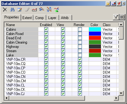
A screenshot of a Database Editor showing various geographic features like cabins, roads, and lakes. Each feature has columns for enabled, view, render, color, and class. Most features are enabled.

3. The new vectors are the basis of a resort development on the bluff southeast of the lake.
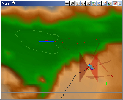
Computer-generated topographic map with green, brown, and red areas, overlaying contour lines, and directional markers.

4. The black Highway vector leads into the development from the southwest. The green Cabin Clearing surrounds the blue Cabin Road, aqua blue Cabins points, and red Dead End vector.
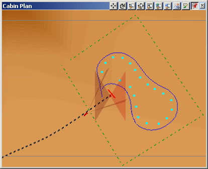
A computer screen showing a 3D cabin plan with various tools and controls. The plan features a kidney-shaped outline with blue dots and a dotted black line intersecting a green dashed square.

5. Go to the Terrain Task Mode. Select the Terraffectors category and Add Component from Gallery.
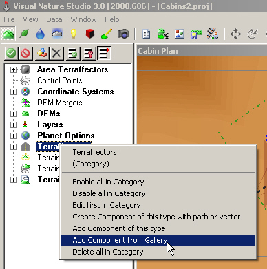
A screenshot of the Visual Nature Studio 3.0 software interface showing a right-click menu with options for terrain factors, including "Add Component From Gallery," highlighted by a cursor.

6. Load the 2 Lane Highway Component from the Component Gallery. Accept the default scaling option and expand the Terraffectors category.
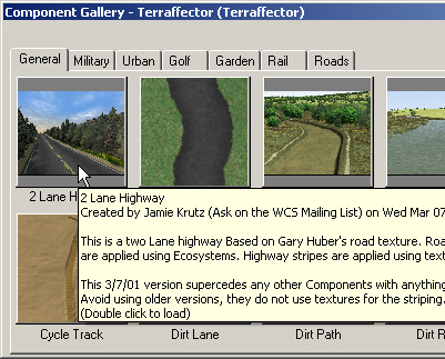
A software interface window labeled "Component Gallery - Terraffecter" displays various road textures under tabs like "General," "Military," "Urban," etc. A description of a 2 Lane Highway texture is highlighted.

. Expand the Vectors category in the lower S@G tab and copy the Highway vector to the 2 Lane Highway Terraffector.
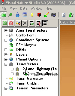
A computer screen displaying the Visual Nature Studio 3.0 software interface, showcasing various options like Area Terraflectors, Coordinate Systems, DEMs, and Terrain Parameters in a sidebar menu.

8. Save the project and render a Cabin Plan preview.
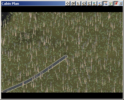
A computer screen displays a digital plan named "Cabin Plan" showing a road amidst a forested area with scattered trees. Various tool icons are located at the top.

9. Go to the Land Cover Task Mode and expand the Ecosystems category. In addition to the Grassland and Pine Burn Ecosystems we started with, the highway Terraffector has added more.
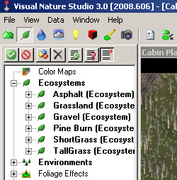
Screenshot of Visual Nature Studio 3.0 interface displaying a sidebar with various ecosystem color map options, including Asphalt, Grassland, Gravel, Pine Burn, ShortGrass, and TallGrass.

10. This is a new housing development, so we’ll use the ShortGrass Ecosystem to fill the clearing in the forest. Copy the Cabin Clearing vector from the lower S@G tab to the ShortGrass Ecosystem.
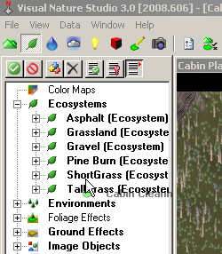
Screenshot of Visual Nature Studio 3.0 software interface showing the Color Maps menu with options for different ecosystems like Asphalt, Grassland, Gravel, Pine Burn, Short Grass, and Tall Grass.

11. Expand the ShortGrass Ecosystem and you’ll see the Cabin Clearing vector at the bottom of the list.
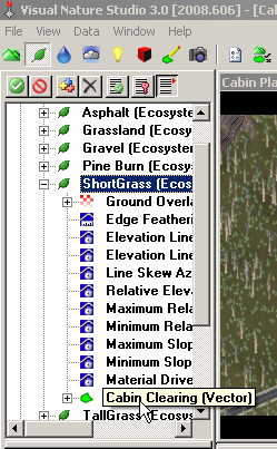
A screenshot of a software interface showing a list of ecosystem options, including ShortGrass, Ground Overlay, and Cabin Clearing. The ShortGrass option is highlighted, and the Cabin Clearing option is selected.

12. Save the project and render a preview.
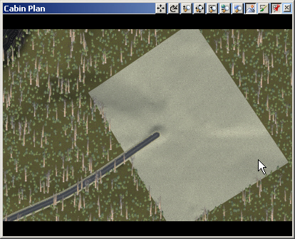
Aerial view of a virtual landscape with a road partially entering an undefined, flat, gray area. The cursor is located on the gray area, and there are various toolbar icons at the top.

13. Open the Road End Plan Camera in the upper left view. Render a preview.
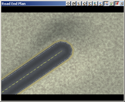
A screenshot of a road design plan, showing the endpoint of a single-lane road with a rounded end, viewed from above.

14. Terraffectors affect terrain outward from the controlling vector, including the ends. This can make for rather unrealistic road terminations. To flatten out the end of the road, we’ll use Revert, a Terraffector from the Component Gallery. Go to the Terrain Task Mode. Select the Terraffectors category and Add Component from Gallery.
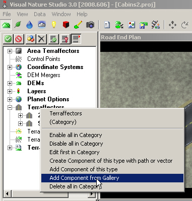
Screenshot of Visual Nature Studio 3.0 software. The "Terrafractors" category is selected, and a context menu shows the option "Add Component from Gallery" highlighted.

15. Load Revert from the Component Gallery.
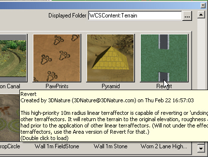
A computer screen displaying a folder named "WCSContent: Terrain" with various terrain features such as "PawPrints" and "Pyramid." A detailed tooltip describing the "Revert" feature is visible.

16. Add the Dead End vector to the Revert Terraffector.
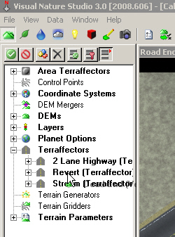
A screenshot of the Visual Nature Studio 3.0 interface displaying a toolbar, menu panel with terrain modification options like "Area Terraflectors" and "Layers", and part of a highway terrain model.

17. Save the project and render a preview.
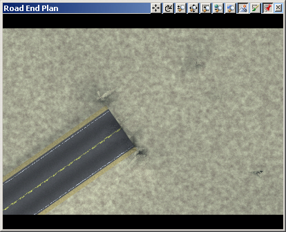
An image depicting the end of a paved road extending into a rough, sandy terrain displayed on a computer screen with a toolbar at the top.

18. Open the Road Camera in the upper left view. Render a preview.
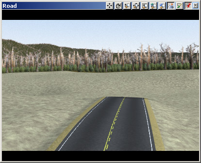
A computer-generated image of a road extending into a grassy terrain with a forested area in the background.

19. Switch the Terraffector Editor to the 2 Lane Highway Component. On the Elevation page, elevation is Relative to Vector Elevation, which is what we want. Edit Cross-section profile.
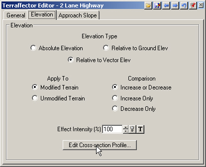
Screenshot of the Terrafector Editor software interface showing options for elevation adjustment, including elevation type, application to terrain, and effect intensity with an option to edit cross-section profile.

20. The centerline of the road starts at the vector elevation, at 0 meters. The associated Asphalt Ecosystem renders left of the point. The next point is about 2.7 meters away from the centerline and slightly lower. It also has the Asphalt Ecosystem, so Asphalt renders between this point and the first point. The third point renders Asphalt to the second point. Gravel comes next. Then ShortGrass. Last is TallGrass with some Ecosystem Mixing to blend the TallGrass with the surrounding Ecosystem. At about 7.6 meters the Terraffector stops and the approach slope takes over. Close the profile.
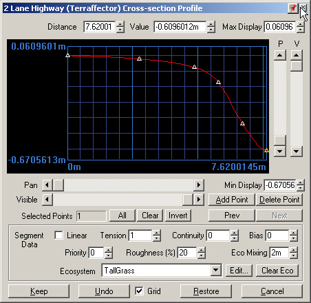
A computer software interface displaying a 2 Lane Highway cross-section profile with various data points and options for editing the profile, including tension, roughness, and ecosystem settings.

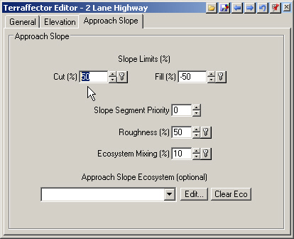
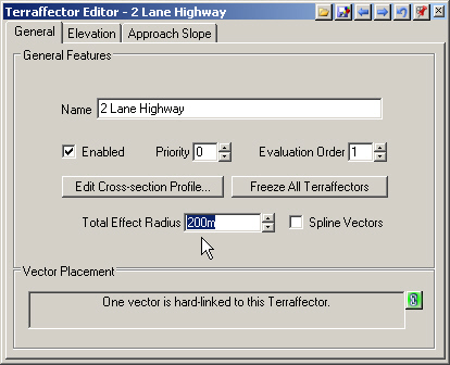
21. Go to the Approach Slope page. Cut and Fill control how the Terraffector changes the terrain between the edge of the Terraffector and the Total Effect Radius distance on the General page.
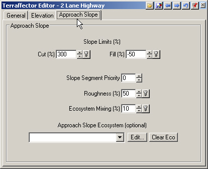
Screenshot of Terraffector Editor interface displaying settings related to the approach slope, including slope limits, slope segment priority, roughness, ecosystem mixing, and approach slope ecosystem.
Screenshot of the Terrafector Editor for a 2 Lane Highway, displaying options for general features, vector placement, and settings like priority, total effect radius, and enabling spline vectors.

22. Change the Cut to a 50% slope.

Screenshot of the Terrafector Editor "Approach Slope" settings tab for a 2 Lane Highway. The settings include slope limits, cut and fill percentages, slope segment priority, roughness, and ecosystem mixing.

23. Open another Road Camera in the upper right view for comparison. Save the project and render a preview. The outside bank of the left ditch is now less steep and more realistic.
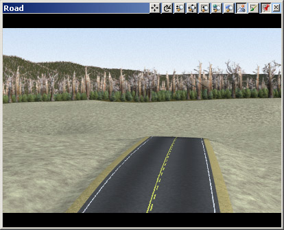
A computer-generated image of a road extending into a forest with bare trees and green undergrowth. The scene is displayed on a screen with a toolbar at the top.
Scroll to top
Skip to content