Getting Started with VNS 3: Draping Images on Terrain
Part 4A. Color Maps
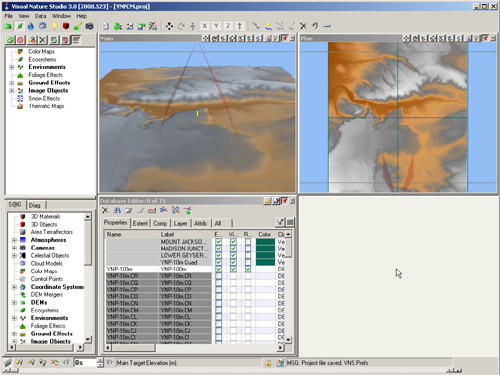
1. Go to the File menu and open the YNP project from the recent projects list. This is the project we created in the last tutorial. Return the Main camera to its default location. Open the Plan Camera in the right view. Save the project as YNPCM.
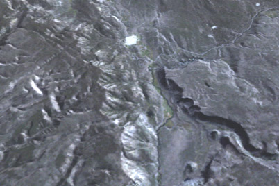
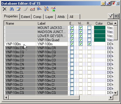
2. Open the Database Editor and you’ll see the YNP-100m DEM enabled, the one we created for higher elevation viewpoints. The 10-meter DEMs are disabled. We’re looking at terrain near the western border of Yellowstone National Park, just east of the town of West Yellowstone, Montana. We’re going to import a corrected color satellite image of the Yellowstone area. The image will be draped over the terrain as a Color Map.
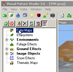
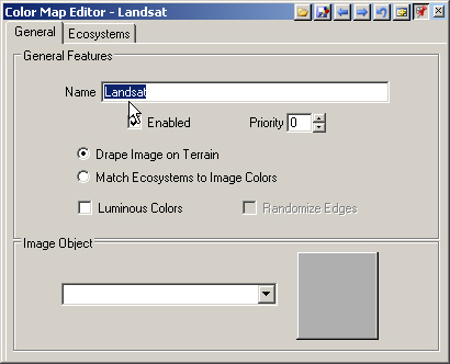
3. Go to the Land Cover Task Mode and double-click the Color Map category to create a new Component.
4. Rename the Color Map Landsat. We’ll use the Image Object dropdown list to add the satellite photo, but let’s first copy the image to a convenient location on the hard drive.
5. Open your file explorer of choice to the VNS 3 DVD image folder. Also find the YNP project folder on your hard drive.
6. Copy YNPLandsat.tif to the YNP folder. The VNS project will remember where this file was loaded from when we add it to the project. If we load it from the DVD, VNS will try to find it there every time the project is opened. Copying it to the project folder keeps it with the project.
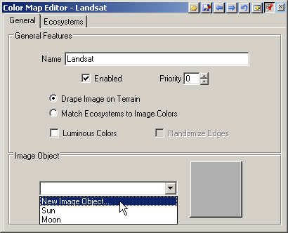
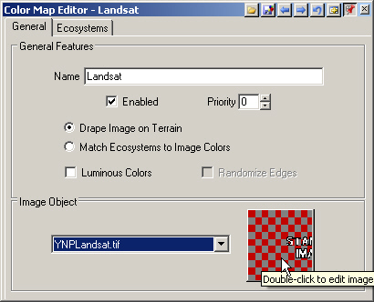
7. Back in the VNS Color Map Editor, expand the Image Object dropdown list and add a New Image Object.
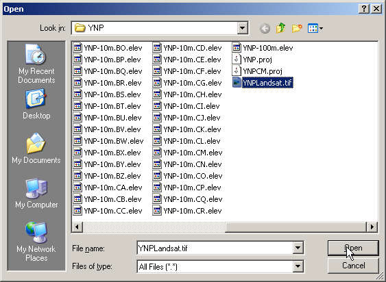
8. Navigate to the YNP project folder and choose YNPLandsat.tif.
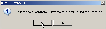
9. The image is a georeferenced TIFF, or GeoTIFF, with a coordinate system different than the one we’re currently using. Make it the new default Coordinate System.
10. After an image is imported, its thumbnail normally appears in the thumbnail window. For larger images handled by the Image Manager, a checkerboard stand-in image appears.
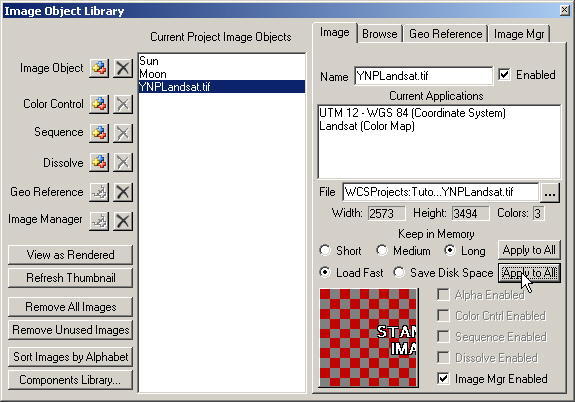
11. Double-click the thumbnail to open the Image Object Library. Enable Load Fast and click Apply to All. In the Current Applications section you’ll see that the image is associated with the UTM 12 – WGS 84 Coordinate System and Landsat Color Map.
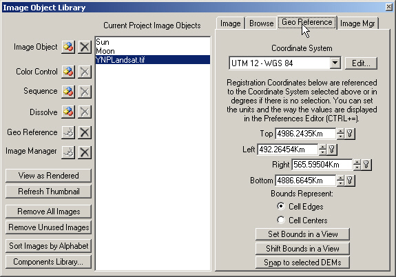
12. The Geo Reference page shows the Coordinate System and bounds.
13. This page also has tools for georeferencing an image that isn’t already georeferenced. With Set Bounds in a View, you can click opposite corners on the terrain where we want to place the image. Shift Bounds in a View is very handy for making adjustments, something even georeferenced images need sometimes. Snap to selected DEMs is great when working with USGS Digital Orthophoto Quadrangles, or DOQs, and USGS Digital Raster Graphics (DRGs).
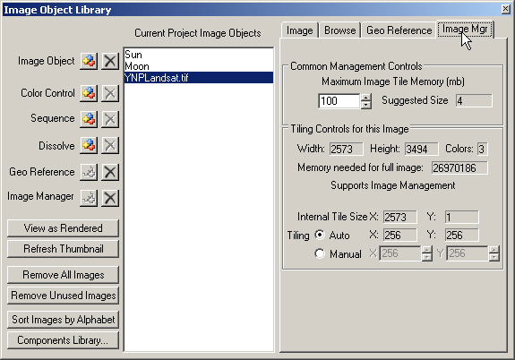
14. The Image Manager is automatically added by VNS when it senses the need. It tiles the image at render time, allowing you to use very large images that would normally be unrenderable because of their memory requirements. Read more about it in the Interactive Reference Manual. Close the library.
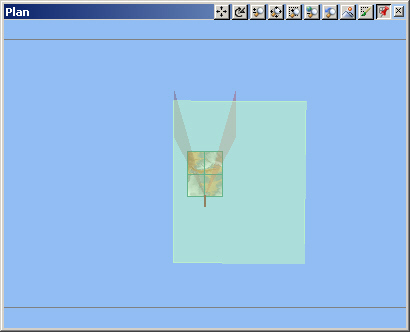
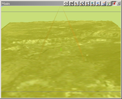
15. Realtime views show the active Landsat Color Map highlighted. Zoom back in the Plan view to see the Color Map bounds.
16. Return to the Plan Camera to its default position.
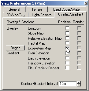
17. Let’s add the Landsat Color Map as a realtime view overlay. Open the Plan View Preferences to the Overlay/Gradient page and check Ecosystem Map.
18. The Status window will show Generate TexMaps as the overlay is generated.
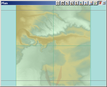
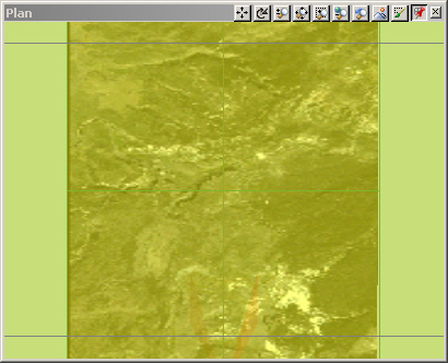
19. When VNS is finished, the Plan view will refresh with the overlay.
20. Repeat the process for the Main view: popup menu, View Preferences, Overlay/Gradient, and Ecosystem Map. There will be less delay generating the image because it’s already in memory. Image detail is a function of terrain resolution. Higher resolution terrain will show more detail in the overlay.
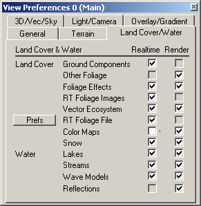
21. The Color Map is getting in the way of our realtime views, so let’s hide it. Go to the View Preferences Land Cover/Water page and deselect the Realtime Color Maps box.
22. Select the other view to switch to its preferences and deselect the Realtime Color Maps box.
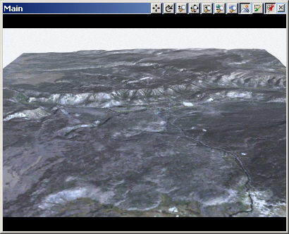
23. Render a Main camera preview. All that’s left is to create a camera path to fly us across the terrain.